
(a)
Show that the given circuit satisfies Kirchhoff’s current law at junction terminals x-y.
(a)
Answer to Problem 1P
Yes, the given circuit satisfies Kirchhoff’s current law at junction terminals x-y.
Explanation of Solution
Given data:
Refer to Figure given in the textbook.
The voltage delivered by the source is
PSPICE Simulation:
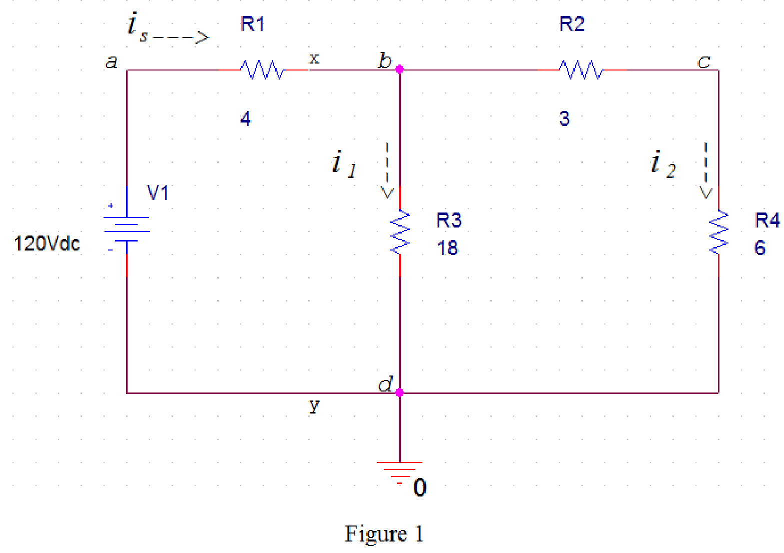
Draw the circuit diagram in PSpice as shown in Figure 1.
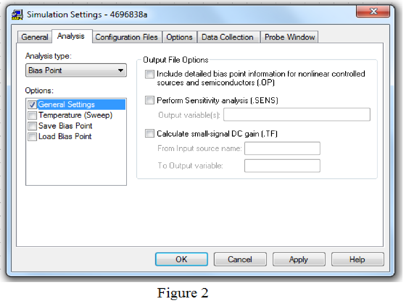
Save the circuit and provide the Simulation Settings as shown in Figure 2.
Now run the simulation and the results will be displayed as shown in Figure 3 by enabling the “Enable Bias Current Display” icon.
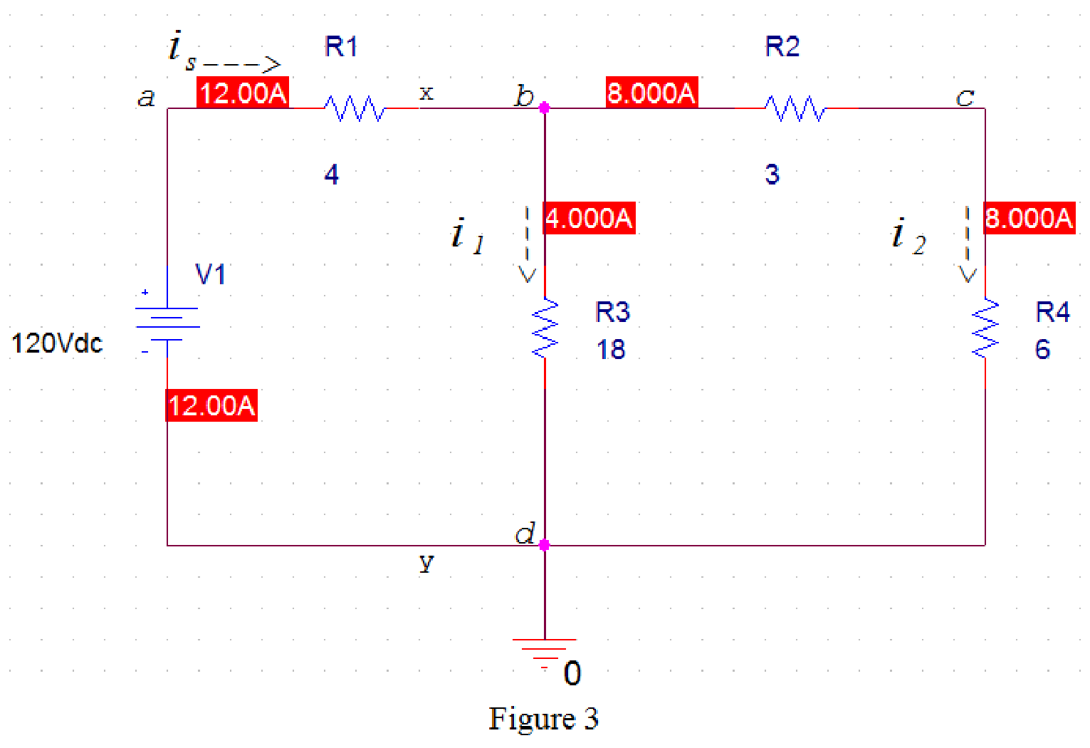
From Figure 3, source current
Kirchhoff’s current law states that the current entering the node is equal to the current leaving the node.
In Figure 3, apply Kirchhoff current law at node b. Therefore,
Rearrange the equation (1) as follows,
Substitute
Hence, the given circuit satisfies Kirchhoff’s current law at junction terminals x-y.
Conclusion:
Thus, yes, the given circuit satisfies Kirchhoff’s current law at junction terminals x-y.
(b)
Show that the given circuit satisfies Kirchhoff’s voltage law.
(b)
Answer to Problem 1P
Yes, the given circuit satisfies Kirchhoff’s voltage law.
Explanation of Solution
Given data:
Refer to Figure given in the textbook.
Voltage delivered by the source is
PSPICE Simulation:
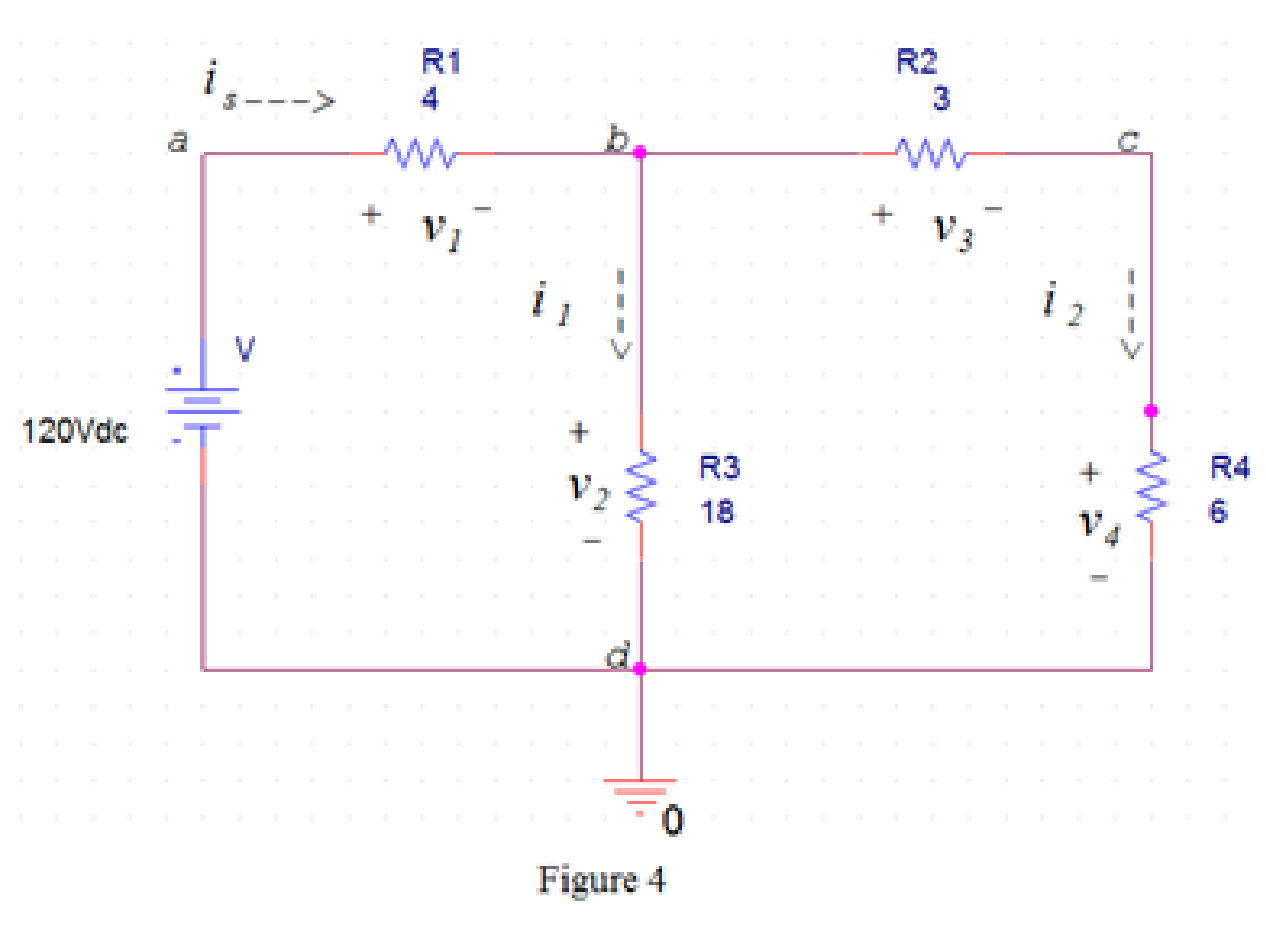
Draw the circuit diagram in PSpice as shown in Figure 4.
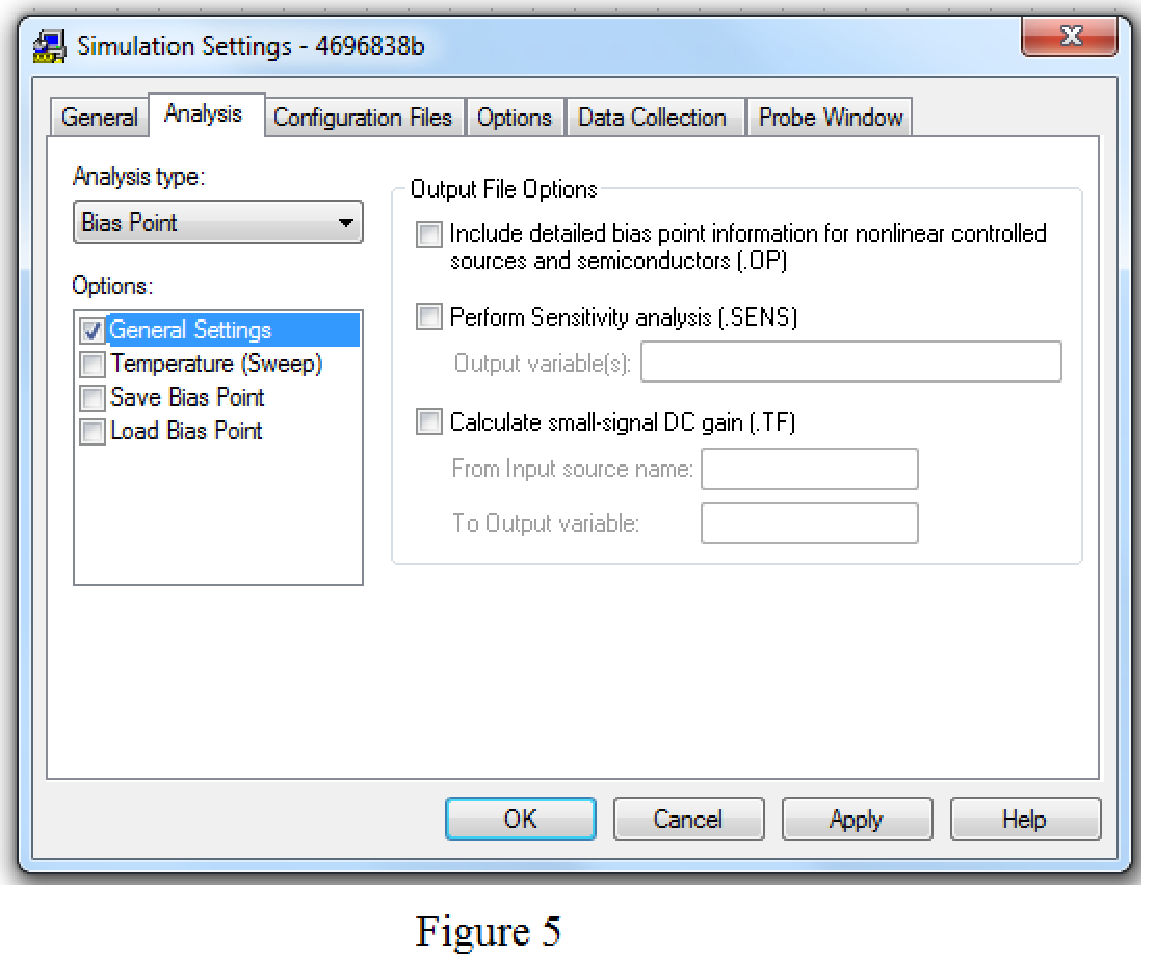
Save the circuit and provide the Simulation Settings as shown in Figure 5.
Now run the simulation and the results will be displayed as shown in Figure 3 by enabling the “Enable Bias Current Display” icon and “Enable Bias Voltage Display” icon.
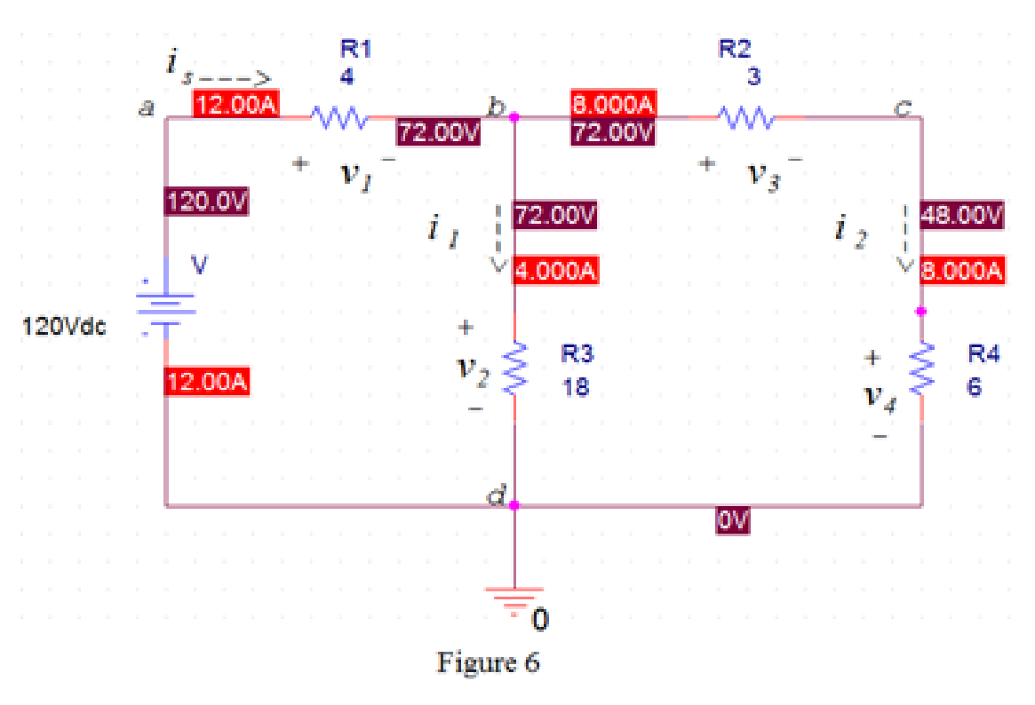
From Figure 6, the voltage
The voltage
The voltage
The voltage
Kirchhoff’s voltage law states that the sum of the voltage rise around any closed loop must be equal to the sum of voltage drops around that loop.
In Figure 6, apply Kirchhoff’s voltage law to the loop abda.
From Figure 6, the source voltage
Substitute
In Figure 6, apply Kirchhoff’s voltage law to the loop bcdb.
Substitute
In Figure 6, apply Kirchhoff’s voltage law to the loop abcda.
Substitute
Hence, the given circuit satisfies Kirchhoff’s voltage law around every closed loop.
Conclusion:
Thus, yes, the given circuit satisfies Kirchhoff’s voltage law.
Want to see more full solutions like this?
Chapter 3 Solutions
Electric Circuits (10th Edition)

 Introductory Circuit Analysis (13th Edition)Electrical EngineeringISBN:9780133923605Author:Robert L. BoylestadPublisher:PEARSON
 Delmar's Standard Textbook Of ElectricityElectrical EngineeringISBN:9781337900348Author:Stephen L. HermanPublisher:Cengage Learning
 Programmable Logic ControllersElectrical EngineeringISBN:9780073373843Author:Frank D. PetruzellaPublisher:McGraw-Hill Education
 Fundamentals of Electric CircuitsElectrical EngineeringISBN:9780078028229Author:Charles K Alexander, Matthew SadikuPublisher:McGraw-Hill Education
 Electric Circuits. (11th Edition)Electrical EngineeringISBN:9780134746968Author:James W. Nilsson, Susan RiedelPublisher:PEARSON
 Engineering ElectromagneticsElectrical EngineeringISBN:9780078028151Author:Hayt, William H. (william Hart), Jr, BUCK, John A.Publisher:Mcgraw-hill Education,