
EBK ELECTRICAL ENGINEERING
7th Edition
ISBN: 8220106714201
Author: HAMBLEY
Publisher: YUZU
expand_more
expand_more
format_list_bulleted
Videos
Textbook Question
Chapter 3, Problem 3.24P
Find the equivalent capacitance for each of the circuits shown in Figure P3.24.
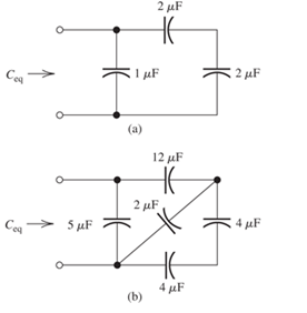
Figure P3.24
Expert Solution & Answer

Trending nowThis is a popular solution!

Learn your wayIncludes step-by-step video

schedule06:13
Students have asked these similar questions
A variable capacitance and a resistance of 290 ohm are connected in series across a 110-V; 60-Hz
supply. Draw the complex or locus of impedance and current as the capacitance changes from 6uF to 32
uF. From the diagram, find
the capacitance to give a current of 0.6 A and
the current when the
capacitance is 11 uF.
4- Electrical failure of insulators occurs due to
and
5- The other name of self-capacitance in a string of suspension insulators is
......
It is required to grade a string having seven suspension insulators. If the pin to earth capacitance are all equal to C, determine the line to pin capacitance that would give the same voltage across each insulator (C1, C2, …….C6) of the string.
Chapter 3 Solutions
EBK ELECTRICAL ENGINEERING
Ch. 3 - What is a dielectric material? Give two examples.Ch. 3 - Briefly discuss how current can flow “through” a...Ch. 3 - What current flows through an ideal capacitor if...Ch. 3 - Describe the internal construction of capacitors.Ch. 3 - A voltage of 50 V appears across a 10F capacitor....Ch. 3 - A 2000F capacitor, initially charged to 100V, is...Ch. 3 - A 5F Capacitor ischarged to 1000 V. Determine the...Ch. 3 - The voltage across a 10F capacitor is given by v...Ch. 3 - The voltage across a 1F capacitor is given by...Ch. 3 - Prior to t = 0, a 100F capacitance is uncharged...
Ch. 3 - The current through a 0.5F capacitor is shown in...Ch. 3 - Determine the capacitor voltage, power, and stored...Ch. 3 - A current given by i(t)=Imcos(t) flows through a...Ch. 3 - The current through a 3F capacitor is shown in...Ch. 3 - A constant (dc) current i(t)=3 mA flows into a 50F...Ch. 3 - The energy stored in a 2F capacitor is 200 J and...Ch. 3 - At t=t0 the voltage across a certain capacitance...Ch. 3 - An unusual capacitor has a capacitance that is a...Ch. 3 - For a resistor, what resistance corresponds to a...Ch. 3 - Suppose we have a very large capacitance (ideally,...Ch. 3 - We want to store sufficient energy in a 001-F...Ch. 3 - A 100F capacitor has a voltage given by v(t)=1010...Ch. 3 - How are capacitances combined in series and in...Ch. 3 - Find the equivalent capacitance for each of the...Ch. 3 - Find the equivalent capacitance between terminals...Ch. 3 - A network has a 5F capacitance in series with the...Ch. 3 - What are the minimum and maximum values of...Ch. 3 - Two initially uncharged capacitors C1=15F and...Ch. 3 - Suppose that we are designing a cardiac pacemaker...Ch. 3 - Suppose that we have two 100F capacitors One is...Ch. 3 - Determine the capacitance of a parallel-plate...Ch. 3 - A 100-pF capacitor is constructed of parallel...Ch. 3 - We have a parallel-plate capacitor with plates of...Ch. 3 - Suppose that we have a 1000-pF parallel-plate...Ch. 3 - Two 1F capacitors have an initial voltage of 100 V...Ch. 3 - Prob. 3.36PCh. 3 - Prob. 3.37PCh. 3 - A parallel-plate capacitor is used as a vibration...Ch. 3 - A 0.1F capacitor has a parasitic series resistance...Ch. 3 - Prob. 3.40PCh. 3 - Briefly discuss how inductors are constructed.Ch. 3 - The current flowing through an inductor is...Ch. 3 - If the current through an ideal inductor is...Ch. 3 - Briefly discuss the fluid-flow analogy for an...Ch. 3 - The current flowing through a 2-H inductance is...Ch. 3 - The current flowing through a 100-mH inductance is...Ch. 3 - The current flowing through a 2-H inductance is...Ch. 3 - The voltage across a 2-H inductance is shown in...Ch. 3 - The voltage across a 10 H inductance is given by...Ch. 3 - A 2-H inductance has i(0) = 0 and v(t)=texp(t) for...Ch. 3 - A constant voltage of 10V is applied to a 50H...Ch. 3 - At t = 0, the current flowing in a 05-H inductance...Ch. 3 - The current through a 100-mH inductance is given...Ch. 3 - Prior to t= 0, the current in a 2-H inductance is...Ch. 3 - At t= 0, a constant 5-V voltage source is applied...Ch. 3 - Prob. 3.56PCh. 3 - Al t= 5 s, the energy stored in a 2-H inductor is...Ch. 3 - What value of inductance (having zero initial...Ch. 3 - To what circuit element does a very large...Ch. 3 - The voltage across an inductance L is given by...Ch. 3 - Discuss how inductances are combined in series and...Ch. 3 - Determine the equivalent inductance for each of...Ch. 3 - Find the equivalent inductance for each of the...Ch. 3 - What is the maximum inductance that can be...Ch. 3 - Suppose we want to combine (in series or in...Ch. 3 - Prob. 3.66PCh. 3 - Two inductances L1=1H and L2=2H are connected in...Ch. 3 - A 10-mH inductor has a parasitic series resistance...Ch. 3 - Draw the equivalent circuit for a real inductor,...Ch. 3 - Suppose that the equivalent circuit shown in...Ch. 3 - Consider the circuit shown in Figure P3.71 in...Ch. 3 - The circuit shown in Figure P3.72 has...Ch. 3 - Describe briefly the physical basis for mutual...Ch. 3 - The mutually coupled inductances in Figure P3.74...Ch. 3 - Repeat Problem P3.74 with the dot placed at the...Ch. 3 - a. Derive an expression for the equivalent...Ch. 3 - Consider the parallel inductors shown in Figure...Ch. 3 - Consider the mutually coupled inductors shown in...Ch. 3 - Mutually coupled inductances have...Ch. 3 - The current through a 200-mH inductance is given...Ch. 3 - A 1-H inductance has iL(0)=0 and vL(t)=texp(t) for...Ch. 3 - The current flowing through a 10F capacitor having...Ch. 3 - Determine the equivalent capacitance Ceq for...Ch. 3 - A certain parallel-plate capacitor has plate...Ch. 3 - A 2-mH inductance has iab=0.3sin(2000t)A . Find an...Ch. 3 - Determine the equivalent inductance Leq between...Ch. 3 - Given that vc(t)=10sin(1000t)V , find vs(t)in the...Ch. 3 - Prob. 3.7PTCh. 3 - The current flowing through a 20F capacitor having...
Additional Engineering Textbook Solutions
Find more solutions based on key concepts
Find {he unknown voltage source and resistor for the networks in Fig. 5.110. First combine the series voltage s...
Introductory Circuit Analysis (13th Edition)
The switch in the bottom loop of Fig. P6.1 is closed at t = 0 and then opened at a later time t1. What is the d...
Fundamentals of Applied Electromagnetics (7th Edition)
The reaction
A + B → 2C
takes place in an unsteady CSTR. The feed is only A and B in equimolar proportions. Whi...
Elements of Chemical Reaction Engineering (5th Edition) (Prentice Hall International Series in the Physical and Chemical Engineering Sciences)
1. In 2001 , the first iPodTM by Apple had a rated battery life of 10 hours (h) to run audio files. The 6th mod...
Thinking Like an Engineer: An Active Learning Approach (4th Edition)
How high can you count with four decimal digits?
Digital Fundamentals (11th Edition)
When displaying a Java applet, the browser invokes the _____ to interpret the bytecode into the appropriate mac...
Web Development and Design Foundations with HTML5 (8th Edition)
Knowledge Booster


Learn more about
Need a deep-dive on the concept behind this application? Look no further. Learn more about this topic, electrical-engineering and related others by exploring similar questions and additional content below.Similar questions
- For the circuit given in Figure-2, let the switch was initially closed at position-1 for a 5T time and then the switch is moved to position-2 and left there. Determine: i. Draw capacitor charging circuit and time constant for charging circuit. ii. Expression for vc and ic while switch is in position-1. iii. Compute vc and ic at t = 1T time while switch is at position-1. iv. Time constant for discharging circuit and draw discharging circuit. v. Expression for vc and ic while switch is at position-2. vi. Compute vc and ic at t = 1T while switch is at position-2. vii. Sketch the voltage and current plot for charging and discharging of capacitor and indicate voltage and currents points on the plot. 10 kΩ ( 15 kN R1 R3 E R2 5 kN E= 200V Figure-2 C= 20.75miyu Farrow_forwardDerive the expressions of voltages across resistor and capacitor and the current through the circuit in charging and discharging phases of an RC circuit excited by DC voltage. Name some uses of transient currents. 2.arrow_forwardhow do i calculate the inverse capacitance and its uncertainty if the capacitance value 1.8748+/- 0.0006. please show steps im using this example to do my other values.arrow_forward
- 1. Enumerate five formulas for series-parallel capacitances across Vt source and draw the circuit. 2. Enumerate five formulas for parallel-series capacitances across Vt source and draw the circuit.arrow_forwardDiscuss how inductances are combined in series and in parallel. Compare with how resistances are combined.arrow_forwarda) We assume that the switch is on. Calculate the reactance values and find the charging current in the circuit below. Is the circuit capacitive or inductive? Show that the voltage across the capacitance can be slightly larger than the source voltage U. (This is called the Ferranti effect and means that we can get a voltage rise beyond overhead lines with small loads. This is mostly relevant at the highest voltage levels. The frequency f is 50Hz, and assume voltage U= √2⋅24kVarrow_forward
- write down the measure capacitance on your bench figure.1arrow_forwardgive definition and explanation about Capacitance meterarrow_forward3-10 A0.25-F capacitor has a current waveform i(t) as shown in Figure P3–10. Determine and plot the voltage waveform v(t) as a function of time. The capacitor is initially a and plot the voltage waveform v(t) as a function of time. The capacitor is imu uncharged. FIGURE P3-10 ilt) 4 A 6. -4 Aarrow_forward
- How active components are different from passive electronic components explain with examples. How are electrolytic capacitors constructed? Explain how they are categories as polarized and non-polarized electrolytic capacitors.arrow_forwardThe network Nc shown below in Figure 1.99(a) contains a combination of scaled capaci- tors in series and parallel connections. Using the vahues as shown, you are asked to do the following. (a) Calculate the value of the terminal capacitance Cab at terminals a-b. (b) To obtain an equivalent capacitance Ceq of 1.5F, Nc is to be placed either in series with a capacitance Cz as shown in Figure 1.99(b) or in parallel with Cx as shown in Figure 1.99(c). Determine which connection is correct and calculate the value of C; that will produce the value of 1.5F for Ceg- 4F 2F 3F 1F C OF (a) N. N. 2. (b) (c) Figure 1.99 (a) Capacitor combo Nc (b) Nc in series with C, (c) Ne in parallel with C,arrow_forwardState the phase relationship between current and voltage for a resistance, for an inductance, and for a capacitance.arrow_forward
arrow_back_ios
SEE MORE QUESTIONS
arrow_forward_ios
Recommended textbooks for you
 Introductory Circuit Analysis (13th Edition)Electrical EngineeringISBN:9780133923605Author:Robert L. BoylestadPublisher:PEARSON
 Delmar's Standard Textbook Of ElectricityElectrical EngineeringISBN:9781337900348Author:Stephen L. HermanPublisher:Cengage Learning
 Programmable Logic ControllersElectrical EngineeringISBN:9780073373843Author:Frank D. PetruzellaPublisher:McGraw-Hill Education
 Fundamentals of Electric CircuitsElectrical EngineeringISBN:9780078028229Author:Charles K Alexander, Matthew SadikuPublisher:McGraw-Hill Education
 Electric Circuits. (11th Edition)Electrical EngineeringISBN:9780134746968Author:James W. Nilsson, Susan RiedelPublisher:PEARSON
 Engineering ElectromagneticsElectrical EngineeringISBN:9780078028151Author:Hayt, William H. (william Hart), Jr, BUCK, John A.Publisher:Mcgraw-hill Education,
Introductory Circuit Analysis (13th Edition)
Electrical Engineering
ISBN:9780133923605
Author:Robert L. Boylestad
Publisher:PEARSON
Delmar's Standard Textbook Of Electricity
Electrical Engineering
ISBN:9781337900348
Author:Stephen L. Herman
Publisher:Cengage Learning
Programmable Logic Controllers
Electrical Engineering
ISBN:9780073373843
Author:Frank D. Petruzella
Publisher:McGraw-Hill Education
Fundamentals of Electric Circuits
Electrical Engineering
ISBN:9780078028229
Author:Charles K Alexander, Matthew Sadiku
Publisher:McGraw-Hill Education
Electric Circuits. (11th Edition)
Electrical Engineering
ISBN:9780134746968
Author:James W. Nilsson, Susan Riedel
Publisher:PEARSON
Engineering Electromagnetics
Electrical Engineering
ISBN:9780078028151
Author:Hayt, William H. (william Hart), Jr, BUCK, John A.
Publisher:Mcgraw-hill Education,
02 - Sinusoidal AC Voltage Sources in Circuits, Part 1; Author: Math and Science;https://www.youtube.com/watch?v=8zMiIHVMfaw;License: Standard Youtube License