
Electrical Engineering: Principles & Applications (7th Edition)
7th Edition
ISBN: 9780134484143
Author: Allan R. Hambley
Publisher: PEARSON
expand_more
expand_more
format_list_bulleted
Concept explainers
Videos
Textbook Question
thumb_up100%
Chapter 3, Problem 3.28P
Two initially uncharged capacitors
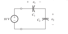
Figure P3.28
Expert Solution & Answer
Want to see the full answer?
Check out a sample textbook solution
Students have asked these similar questions
Consider the mutually coupled inductors shown in Figure 3.25(a), with a short connected across the terminals of L2. Derive an expression for the equivalent inductance seen looking into the terminals of L1.
A potential difference of V = 58.0 V is applied across a circuit with capacitances C1 = 4.7 nF, C2 = 3.1 nF, and C3= 1.3 nF, as shown in the figure.a) What is the magnitude and sign of q3l, the charge on the left plate of C3 (marked by point A)?
b) What is the electric potential difference, V3, across C3?
c) What is the magnitude and sign of the charge q2r, on the right plate of C2 (marked by point B)?
Suppose that a parallel-plate capacitor has a dielectric that breaks down if the electric field exceeds K V/m. Thus, the maximum voltage rating of the capacitor is V max =K d, where d is the separation between the plates. In working Problem P3.33, we find that the maximum energy that can be stored is w max = 1 2 ∈ r ∈ 0 K 2 (Vol) in which Vol is the volume of the dielectric. Given that K=32× 10 5 V/m and that ∈ r =1 (the approximate values for air), find the dimensions of a parallel-plate capacitor having square plates if it is desired to store 1 mJ at a voltage of 1000 V in the least possible volume.
Chapter 3 Solutions
Electrical Engineering: Principles & Applications (7th Edition)
Ch. 3 - What is a dielectric material? Give two examples.Ch. 3 - Briefly discuss how current can flow “through” a...Ch. 3 - What current flows through an ideal capacitor if...Ch. 3 - Describe the internal construction of capacitors.Ch. 3 - A voltage of 50 V appears across a 10F capacitor....Ch. 3 - A 2000F capacitor, initially charged to 100V, is...Ch. 3 - A 5F Capacitor ischarged to 1000 V. Determine the...Ch. 3 - The voltage across a 10F capacitor is given by v...Ch. 3 - The voltage across a 1F capacitor is given by...Ch. 3 - Prior to t = 0, a 100F capacitance is uncharged...
Ch. 3 - The current through a 0.5F capacitor is shown in...Ch. 3 - Determine the capacitor voltage, power, and stored...Ch. 3 - A current given by i(t)=Imcos(t) flows through a...Ch. 3 - The current through a 3F capacitor is shown in...Ch. 3 - A constant (dc) current i(t)=3 mA flows into a 50F...Ch. 3 - The energy stored in a 2F capacitor is 200 J and...Ch. 3 - At t=t0 the voltage across a certain capacitance...Ch. 3 - An unusual capacitor has a capacitance that is a...Ch. 3 - For a resistor, what resistance corresponds to a...Ch. 3 - Suppose we have a very large capacitance (ideally,...Ch. 3 - We want to store sufficient energy in a 001-F...Ch. 3 - A 100F capacitor has a voltage given by v(t)=1010...Ch. 3 - How are capacitances combined in series and in...Ch. 3 - Find the equivalent capacitance for each of the...Ch. 3 - Find the equivalent capacitance between terminals...Ch. 3 - A network has a 5F capacitance in series with the...Ch. 3 - What are the minimum and maximum values of...Ch. 3 - Two initially uncharged capacitors C1=15F and...Ch. 3 - Suppose that we are designing a cardiac pacemaker...Ch. 3 - Suppose that we have two 100F capacitors One is...Ch. 3 - Determine the capacitance of a parallel-plate...Ch. 3 - A 100-pF capacitor is constructed of parallel...Ch. 3 - We have a parallel-plate capacitor with plates of...Ch. 3 - Suppose that we have a 1000-pF parallel-plate...Ch. 3 - Two 1F capacitors have an initial voltage of 100 V...Ch. 3 - Prob. 3.36PCh. 3 - Prob. 3.37PCh. 3 - A parallel-plate capacitor is used as a vibration...Ch. 3 - A 0.1F capacitor has a parasitic series resistance...Ch. 3 - Prob. 3.40PCh. 3 - Briefly discuss how inductors are constructed.Ch. 3 - The current flowing through an inductor is...Ch. 3 - If the current through an ideal inductor is...Ch. 3 - Briefly discuss the fluid-flow analogy for an...Ch. 3 - The current flowing through a 2-H inductance is...Ch. 3 - The current flowing through a 100-mH inductance is...Ch. 3 - The current flowing through a 2-H inductance is...Ch. 3 - The voltage across a 2-H inductance is shown in...Ch. 3 - The voltage across a 10 H inductance is given by...Ch. 3 - A 2-H inductance has i(0) = 0 and v(t)=texp(t) for...Ch. 3 - A constant voltage of 10V is applied to a 50H...Ch. 3 - At t = 0, the current flowing in a 05-H inductance...Ch. 3 - The current through a 100-mH inductance is given...Ch. 3 - Prior to t= 0, the current in a 2-H inductance is...Ch. 3 - At t= 0, a constant 5-V voltage source is applied...Ch. 3 - Prob. 3.56PCh. 3 - Al t= 5 s, the energy stored in a 2-H inductor is...Ch. 3 - What value of inductance (having zero initial...Ch. 3 - To what circuit element does a very large...Ch. 3 - The voltage across an inductance L is given by...Ch. 3 - Discuss how inductances are combined in series and...Ch. 3 - Determine the equivalent inductance for each of...Ch. 3 - Find the equivalent inductance for each of the...Ch. 3 - What is the maximum inductance that can be...Ch. 3 - Suppose we want to combine (in series or in...Ch. 3 - Prob. 3.66PCh. 3 - Two inductances L1=1H and L2=2H are connected in...Ch. 3 - A 10-mH inductor has a parasitic series resistance...Ch. 3 - Draw the equivalent circuit for a real inductor,...Ch. 3 - Suppose that the equivalent circuit shown in...Ch. 3 - Consider the circuit shown in Figure P3.71 in...Ch. 3 - The circuit shown in Figure P3.72 has...Ch. 3 - Describe briefly the physical basis for mutual...Ch. 3 - The mutually coupled inductances in Figure P3.74...Ch. 3 - Repeat Problem P3.74 with the dot placed at the...Ch. 3 - a. Derive an expression for the equivalent...Ch. 3 - Consider the parallel inductors shown in Figure...Ch. 3 - Consider the mutually coupled inductors shown in...Ch. 3 - Mutually coupled inductances have...Ch. 3 - The current through a 200-mH inductance is given...Ch. 3 - A 1-H inductance has iL(0)=0 and vL(t)=texp(t) for...Ch. 3 - The current flowing through a 10F capacitor having...Ch. 3 - Determine the equivalent capacitance Ceq for...Ch. 3 - A certain parallel-plate capacitor has plate...Ch. 3 - A 2-mH inductance has iab=0.3sin(2000t)A . Find an...Ch. 3 - Determine the equivalent inductance Leq between...Ch. 3 - Given that vc(t)=10sin(1000t)V , find vs(t)in the...Ch. 3 - Prob. 3.7PTCh. 3 - The current flowing through a 20F capacitor having...
Knowledge Booster


Learn more about
Need a deep-dive on the concept behind this application? Look no further. Learn more about this topic, electrical-engineering and related others by exploring similar questions and additional content below.Similar questions
- The charges of the 2C, C, 2C capacitance capacitors in the figure are qk, qi and qm, respectively. Accordingly, what kind of relationship is there between qk, qi and qm?arrow_forwardThe figure shows an electrical circuit with an ideal source ε1 = 12 [V], a real source ε2 = 9 [V] and r1 = 1 [Ω], eight resistors and two capacitors. Switches A and B areThey are originally open and the charge on the capacitors is zero. If at t = 0 [s] switch A opens and switch B closes, determine:d) The potential difference of resistor R8 at t = 2.6 [s].e) The time required for the potential difference of the equivalent capacitor to reach the maximum possible value. Justify your answer.arrow_forwardA 10-mH inductor has a parasitic series resistance of R s =1 Ω, as shown in FigureP3.68.a. The current is given by i( t )=0.1 cos( 10 5 t ). Find v R ( t ), v L ( t ), and v(t). In thiscase, for 1-percent accuracy in computing v(t), could the resistance be neglected?b. Repeat if i( t )=0.1 cos( 10t ).arrow_forward
- Capacitance= 4uF2) Determine the time constant of the circuit for the capacities 3) For the capacity value, calculate the estimated time to come to the final state.4) Plot capacitor current and voltage graphs and show if it works in harmony with the time constant you calculated. NOTE: if you want you can use falstad online circuit simulator.arrow_forwardFor the capacitor network shown in Figure(Q2a) above (which has reachedsteady state i.e. on for a very long time), calculate:i. The total capacitance, CT , for the entire networkii. The voltage across capacitor C2iii. The total charge stored across capacitor C2iv. The energy stored in capacitor C2arrow_forwardA potential difference V(t) = V0sin ωt ismaintained across a parallel-plate capacitor withcapacitance C consisting of two circular parallel plates. Athin wire with resistance R connects the centers of the twoplates, allowing charge to leak between plates while theyare charging.(a) Obtain expressions for the leakage current Ires(t) in thethin wire. Use these results to obtain an expression for thecurrent Ireal(t) in the wires connected to the capacitor.(b) Find the displacement current in the space between theplates from the changing electric field between the plates.(c) Compare Ireal(t) with the sum of the displacementChapter 16 | Electromagnetic Waves 733current Id(t) and resistor current Ires(t) between theplates, and explain why the relationship you observe wouldbe expected.arrow_forward
- Two initially uncharged capacitors C 1 = 15 μF and C 2 =10 μF are connected in series. Then, a 10-V source is connected to the series combination, as shown in Figure P3.28. Find the voltages v1 and v2 after the source is applied. [Hint: The charges stored on the two capacitors must be equal, because the current is the same for both capacitors.]arrow_forwardi. How can four 100 kΩ resistors be connected so that the equivalent resistance of the four equals 250 kΩ? Sketch the arrangement, describe the resistor arrangement in words, and justify your picture by calculating the equivalent resistance. ii. Repeat part i. above with four 100 F capacitors and an equivalent capacitance of 75 F.arrow_forwardA 150-volt electromotive force is applied to an RC-series circuit in which the resistance is 1500 ohm and the capacitance is 5 micro Farad (uF). If q(0)=0, find the charge and current at t=0.005 s. charge: q = micro Farad (uF) current: i = milli ampere (mA) Determine the charge as t approaches infinity. charge: q= micro Farad (uF)arrow_forward
- The voltage across an inductance L is given by v( t )= V m cos( ωt ). The current is zero at t=0 .Suppose that is very large ideally, approaching infinity. For this voltage, does the inductance approximate either an open or a short circuit? Explain.arrow_forwardCalculate the gravimetric capacitance of a carbon based electrode with an aqueous electrolyte solution. Assume the surface area of the carbon electrode is 1200 m2/g, and the relative static permittivity of the aqueous electrolyte solution is 80. The permittivity of free space is 8.85 × 10⁻¹² F/m. Indicate any other assumptions you have to make.arrow_forwardVbatt=25 VC1=90 ?CC2=75 ?CC3=60 ?CR1=160 ΩR2=120 Ωt2=21.6 msect3=27 msecConsider the circuit shown below which shows a battery connected to some resistors and capacitors along with some switches which will be toggled opened or closed at different times. The components are listed above. The capacitances are in microCoulombs (?C), the resitances are in Ohms (Ω), and the times are in milliseconds (msec). A stopwatch is started at time t1=0 ms. At that time, switch S1 is closed and all other switches are open and the capacitor is allowed to charge up.(a). What is the charge (in uC) on C1 at the time the stopwatch reads t2=21.6 ms?Ans: 1750 uC(b). What is the current (in mA) through R1 at t2=21.6 ms?Ans: 34.9 mA(c). What is the voltage (in V) across R1 at t2=21.6 ms?Ans: 5.58 V(d). What is the voltage (in V) across C1 at t2=21.6 ms?Ans: 19.4 V(e). What is the energy (in mJ) in C1 at t2=21.6 ms?Ans: 17.0 mJThen, immediately at time t2=21.6 on the stopwatch, switch S1 is thrown open and…arrow_forward
arrow_back_ios
SEE MORE QUESTIONS
arrow_forward_ios
Recommended textbooks for you
 Introductory Circuit Analysis (13th Edition)Electrical EngineeringISBN:9780133923605Author:Robert L. BoylestadPublisher:PEARSON
 Delmar's Standard Textbook Of ElectricityElectrical EngineeringISBN:9781337900348Author:Stephen L. HermanPublisher:Cengage Learning
 Programmable Logic ControllersElectrical EngineeringISBN:9780073373843Author:Frank D. PetruzellaPublisher:McGraw-Hill Education
 Fundamentals of Electric CircuitsElectrical EngineeringISBN:9780078028229Author:Charles K Alexander, Matthew SadikuPublisher:McGraw-Hill Education
 Electric Circuits. (11th Edition)Electrical EngineeringISBN:9780134746968Author:James W. Nilsson, Susan RiedelPublisher:PEARSON
 Engineering ElectromagneticsElectrical EngineeringISBN:9780078028151Author:Hayt, William H. (william Hart), Jr, BUCK, John A.Publisher:Mcgraw-hill Education,
Introductory Circuit Analysis (13th Edition)
Electrical Engineering
ISBN:9780133923605
Author:Robert L. Boylestad
Publisher:PEARSON
Delmar's Standard Textbook Of Electricity
Electrical Engineering
ISBN:9781337900348
Author:Stephen L. Herman
Publisher:Cengage Learning
Programmable Logic Controllers
Electrical Engineering
ISBN:9780073373843
Author:Frank D. Petruzella
Publisher:McGraw-Hill Education
Fundamentals of Electric Circuits
Electrical Engineering
ISBN:9780078028229
Author:Charles K Alexander, Matthew Sadiku
Publisher:McGraw-Hill Education
Electric Circuits. (11th Edition)
Electrical Engineering
ISBN:9780134746968
Author:James W. Nilsson, Susan Riedel
Publisher:PEARSON
Engineering Electromagnetics
Electrical Engineering
ISBN:9780078028151
Author:Hayt, William H. (william Hart), Jr, BUCK, John A.
Publisher:Mcgraw-hill Education,
Lecture - 10 Transmission Line Parameters; Author: nptelhrd;https://www.youtube.com/watch?v=lr1jgbR5ca8;License: Standard YouTube License, CC-BY
Inductance of Three Phase Transmission lines (Symmetrical and Unsymmetrical Configurations); Author: Ravindra Prasad Pendyala;https://www.youtube.com/watch?v=CbFBxjfHYFY;License: Standard Youtube License