
Materials For Civil And Construction Engineers In Si Units
4th Edition
ISBN: 9781292154404
Author: Michael S Mamlouk
Publisher: PEARSON
expand_more
expand_more
format_list_bulleted
Videos
Textbook Question
Chapter 3, Problem 3.34QP
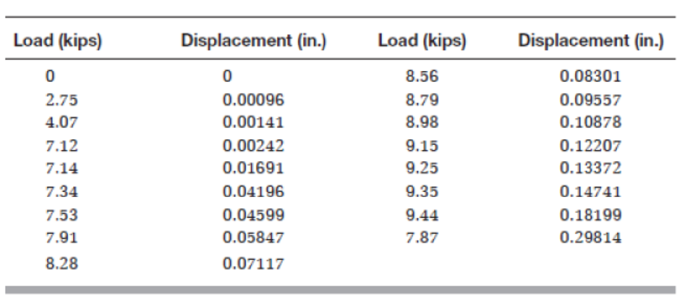
A grade 36 round steel bar with a diameter of 0.5 in. and a gauge length of 2 in. was subjected to tension to rupture following ASTM E-8 test procedure, The load and deformation data were as shown in Table P3.34.
Using a spreadsheet program obtain the Following:
- a. A plot of the stress-strain relationship. Label the axes and show units.
- b. A plot of the linear portion of the stress-strain relationship. Determine modulus of elasticity using the best fit approach.
- c. Proportional limit.
- d. Yield stress.
- e. Ultimate strength.
- f. When the applied load was 4.07 kips, the diameter was measured as 0.499905 in. Determine Poisson’s ratio.
- g. After the rod was broken, the two parts were put together and the diameter at the neck was measured as 0.416012 in. What is the true stress value at fracture? Is the true stress at fracture larger or smaller than the engineering stress at fracture? Why?
- h. Do you expect the true strain at fracture to be larger or smaller than the engineering strain at fracture? Why?
TABLE P3.34
Expert Solution & Answer
Want to see the full answer?
Check out a sample textbook solution
Students have asked these similar questions
A grade 36 round steel bar with a diameter of 0.5 inches and a gauge length of 2 inches wassubjected to tension to rupture following ASTM E-8 test procedure. The load and deformation data wereas shown in the following table:
Using a spreadsheet program obtain the following:a. A plot of the stress-strain relationship. Label the axes and show units.b. A plot of the linear portion of the stress-strain relationship. Determine modulus of elasticity usingthe best fit approach.c. Proportional limit.d. Yield stress.e. Ultimate strength.f. When the applied load was 4.07 kips, the diameter was measured as 0.499905 inches. DeterminePoisson’s ratio.g. After the rod was broken, the two parts were put back together and the diameter of at the neckwas measured as 0.416012 inches. What is the true stress value at fracture? Is the true stress atfracture larger or smaller than the engineering stress at fracture? Why?h. Do you expect the true strain at fracture to be larger or smaller than the…
A round steel bar with a diameter of 12mm and a gauge length of 0.5 mm was subjected to tension to rupture following ASTM E-8 test procedure. The load and deformation data were as shown in Table. Using a spreadsheet program obtain the following:
A plot of the stress–strain relationship. Label the axes and show units.
A plot of the linear portion of the stress–strain relationship. Determine modulus of elasticity using the best fit approach.
Proportional limit.
Yield stress.
Ultimate strength.
When the applied load was 18kN, the diameter was measured as12.7mm Determine Poisson’s ratio.
After the rod was broken, the two parts were put together and the diameter at the neck was measured as 10.6 mm. What is the true stress value at fracture? Is the true stress at fracture larger or smaller than the engineering stress at fracture? Why?
Do you expect the true strain at fracture to be larger or smaller than the engineering strain at fracture? Why?
hree steel bars with a diameter of 25 mm and carbon contents of 0.2, 0.5, and 0.8%, respectively. The specimens were subjected to tension until rupture. The load versus deformation results were as shown in Table P3.19. If the gauge length is 50 mm, determine the following:
The tensile stresses and strains for each specimen at each load increment.
Plot stresses versus strains for all specimens on one graph.
The proportional limit for each specimen.
The 0.2% offset yield strength for each specimen.
The modulus of elasticity for each specimen.
The strain at rupture for each specimen.
Comment on the effect of increasing the carbon content on the following:
Yield strength ii. Modulus of elasticity iii. Ductility
Chapter 3 Solutions
Materials For Civil And Construction Engineers In Si Units
Ch. 3 - What is the chemical composition of steel? What is...Ch. 3 - Why does the ironcarbon phase diagram go only to...Ch. 3 - Draw a simple ironcarbon phase diagram showing the...Ch. 3 - What is the typical maximum percent of carbon in...Ch. 3 - Calculate the amounts and compositions of phases...Ch. 3 - Briefly discuss four heat treatment methods to...Ch. 3 - Define alloy steels. Explain why alloys are added...Ch. 3 - Prob. 3.8QPCh. 3 - Specifically state the shape and size of the...Ch. 3 - What are the typical uses of structural steel?
Ch. 3 - What is the range of thicknesses of cold-formed...Ch. 3 - Why is coil steel used for cold-formed steel...Ch. 3 - If a steel with a 33 ksi yield strength is used...Ch. 3 - Why is reinforcing steel used in concrete? Discuss...Ch. 3 - What is high-performance steel? State two HPS...Ch. 3 - Name three mechanical tests used to measure...Ch. 3 - The following laboratory tests are performed on...Ch. 3 - Sketch the stress-strain behavior of steel, and...Ch. 3 - Three steel bars with a diameter of 25 mm and...Ch. 3 - Three steel bars with a diameter of 0.5 in. and...Ch. 3 - Draw a typical stressstrain relationship for steel...Ch. 3 - Getting measurements from Figure 3.18, determine...Ch. 3 - A steel specimen is tested in tension. The...Ch. 3 - A steel specimen is tested in tension. The...Ch. 3 - A No. 10 steel rebar is tested in tension. By...Ch. 3 - A mild steel specimen originally 300 mm long is...Ch. 3 - A tension stress of 70 ksi was applied on a 12-in....Ch. 3 - A tensile stress is applied along the long axis of...Ch. 3 - A cylindrical steel alloy rod with a 0.5 in....Ch. 3 - A round steel alloy bar with a diameter of 0.75...Ch. 3 - A 19-mm reinforcing steel bar and a gauge length...Ch. 3 - Testing a round steel alloy bar with a diameter of...Ch. 3 - During the tension test on a steel rod within the...Ch. 3 - A grade 36 round steel bar with a diameter of 0.5...Ch. 3 - A high-yield-strength alloy steel bar with a...Ch. 3 - Estimate the cross-sectional area of a 350S125-27...Ch. 3 - An ASTM A615 grade 60 number 10 rebar with a gauge...Ch. 3 - A 32-mm rebar with a gauge length of 200 mm was...Ch. 3 - A steel pipe having a length of 3 ft. an outside...Ch. 3 - A steel pipe having a length of 1 m, an outside...Ch. 3 - A drill rod with a diameter of 10 mm is made of...Ch. 3 - A drill rod with, a diameter of 1/2 in. is made of...Ch. 3 - Prob. 3.43QPCh. 3 - An engineering technician performed a tension test...Ch. 3 - A Charpy V Notch (CVN) test was performed on a...Ch. 3 - Prob. 3.46QPCh. 3 - Prob. 3.47QPCh. 3 - How can the flaws in steel and welds be detected?...Ch. 3 - Determine the welding zone classification of A36...Ch. 3 - Briefly define steel corrosion. What are the four...Ch. 3 - Discuss the main methods used to protect steel...
Knowledge Booster


Learn more about
Need a deep-dive on the concept behind this application? Look no further. Learn more about this topic, civil-engineering and related others by exploring similar questions and additional content below.Similar questions
- An ASTM A615 grade 60 number 10 rebar with a gauge length of 8 in. was subjected to tension to fracture according to ASTM E-8 method. The load and deformation data were as shown in Table .Using a spreadsheet program, obtain the following:a. A plot of the stress–strain relationship. Label the axes and show units.b. A plot of the linear portion of the stress–strain relationship. Determine modulus of elasticity using the best-fit approach.c. Proportional limit.arrow_forwardA steel bar, whose cross section is 0.60 inch by 4.10 inches, was tested in tension. An axial load of P = 31,025 lb. produced a deformation of 0.115 inch over a gauge length of 2.10 inches and a decrease of 0.0080 inch in the 0.60-inch thickness of the bar. a. Determine the lateral strain. b. Determine the axial strain. c. Determine the Poisson’s ratio v. d. Determine the decrease in the 4.05-in. cross-sectional dimension (in inches).arrow_forwardA 32-mm rebar with a gauge length of 200 mm was subjected to tension to fracture according to ASTM E-8 method. The load and deformation data were as shown in TableUsing a spreadsheet program obtain the following:a. A plot of the stress–strain relationship. Label the axes and show units.b. A plot of the linear portion of the stress–strain relationship. Determine modulus of elasticity using the best-fit approach.c. Proportional limit.d. Yield stress.e. Ultimate strength.f. If the rebar is loaded to 390 kN only and then unloaded, what is the permanent change in length?arrow_forward
- A tensile test was performed on a metal specimen with a diameter of 1⁄2 inch and a gage length (the length over which the elongation is measured) of 4 inches. The data were plotted on a load-displacement graph, P vs. ∆L. A best-fit line was drawn through the points, and the slope of the straight-line portion was calculated to be P y∆L 5 1392 kips yin. What is the modulus of elasticity?arrow_forwardWith the dimensions already given, determine the allowable value of the tensile load P, considering the following parameters (The figure shown below is a hanger): 1. The allowable normal stress at the two vertical bolts (bolts 1 and 2) is 160 MPa. 2. The allowable tensile stress in the hanger (see label) is 110 MPa. 3. The allowable tensile stess in the hanger considering the cross section through the horizontal bolt is 75 MPa. 4. The allowable shear stess at the horizontal bolt is 45 MPa. 5. The allowable bearing stress between the washer and the clip angle at the vertical bolts is 65 MPa. 6. The allowable bearing stress at the "shank" of the horizontal bolt is 180 MPa. 7. The allowable shear stress through the clip angle at the vertical bolts is 35 MPa. Note: Draw the Free Body Diagram, include the proper units and round-off the answers to 3 decimal places.arrow_forwardThe rubber band given below is subjected to the following tensile loading. Calculate the minimum thickness of the rubber (tr) and the minimum steel pin diameter (Dpin) so that the structure does not fail. Consider: Allowable tensile strength of the rubber= 20MPa Allowable shear strength of the steel = 200MPa Reflection: 1) How would you solve this problem if a Factor of Safety was given? 2) Are there any other dimensions worth calculating for the rubber belt?arrow_forward
- Determine the strain at yield of a Grade 60 #14 rebar (ASTM A 615). How does this compare to the strain at yield of a Grade 60 #5 rebar?arrow_forwardCalculate the steel ratio that will produce a tension-controlled failure if compressivestrength f’c = 28 MPa and steel yield strength fy the answer is 0.02167 but i don't know how to solve it please helparrow_forwardA 40 mm diameter steel bar is subjected to a tension test. Under a tension load of 276.46 kN, it was observed that the original gage length of 50 mm increased in length by 0.055 mm and the diameter decreased by 0.0105 mm. Compute the modulus of elasticity (MPa).arrow_forward
- A wood specimen was prepared with actual dimensions of 25 mm * 25 mm *150 mm and grain parallel to its length. Displacement was measured over a100 mm gauge length. The specimen was subjected to compression parallel to the grain to failure. The load–deformation results are as shown in Table P10.24. a. Using a computer spreadsheet program, plot the stress–strain relationship.b. Calculate the modulus of elasticity.c. What is the failure stress?arrow_forwardPROBLEM 3A tensile test is performed on a brass specimen 10mm in diameter using a gage length of 50mm. When the tensile load P reaches a value of 20kN, the distance between the gage marks has increased by 0.122 mm. What is the modulus of elasticity? Note: Please show complete solution with FBDarrow_forwardShow complete process. A tensile load of 150 kN is applied to a round metal bar with a diameter of 16 mm and a gage length of 80 mm. Under this load the bar elastically deforms so that the gage length increases to 80.1192 mm and the diameter decreases to 15.89 mm. Determine the modulus of elasticity (in MPa) and Poisson’s ratio for this metal.arrow_forward
arrow_back_ios
SEE MORE QUESTIONS
arrow_forward_ios
Recommended textbooks for you
 Steel Design (Activate Learning with these NEW ti...Civil EngineeringISBN:9781337094740Author:Segui, William T.Publisher:Cengage Learning
Steel Design (Activate Learning with these NEW ti...
Civil Engineering
ISBN:9781337094740
Author:Segui, William T.
Publisher:Cengage Learning
Material Properties 101; Author: Real Engineering;https://www.youtube.com/watch?v=BHZALtqAjeM;License: Standard YouTube License, CC-BY