
Concept explainers
(a)
The number of non reference nodes.
Answer to Problem 3.35HP
The number of non reference nodes is
Explanation of Solution
Calculation:
The given diagram is shown in Figure 1
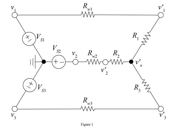
The non reference node is anode that is connected between a voltage node and any other element of the circuit.
From the above figure it is clear that there are in total
Conclusion:
Therefore, the number of non-reference nodes is
(b)
The number of unknown node voltage.
Answer to Problem 3.35HP
The number of unknown node voltages is
Explanation of Solution
Calculation:
From the figure shown in Figure 1, the number of unknown node voltages are
Conclusion:
Therefore, the number of unknown node voltages is
(c)
The value of
Answer to Problem 3.35HP
The value of voltage
Explanation of Solution
Calculation:
Mark the values and redraw the circuit.
The required diagram is shown in Figure 2
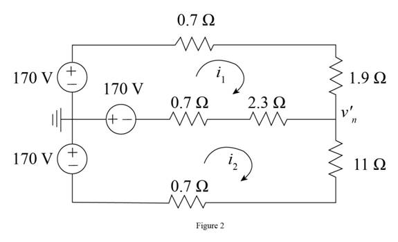
Apply nodal at
The expression for the voltage across the resistance
Substitute
The expression to calculate the voltage
Substitute
The voltage across the resistance
Substitute
The expression for the voltage
Substitute
The voltage across the resistance
Substitute
The expression to calculate the voltage
Substitute
Conclusion:
Therefore, the value of voltage
Want to see more full solutions like this?
Chapter 3 Solutions
Connect 1 Semester Access Card For Principles And Applications Of Electrical Engineering


- Answer the following points in detail and rigorously. Instead of resorting to formulas, develop from basic principles (laws of voltages and currents, definition of electrical power, properties of phasors, among others). a) Show that the complex power consumed by two elements in parallel is the sum of the individual complex powers. Then repeat the procedure but for two elements in series. b What meaning would you give to the P consumed by an element? Which to Q? c) Suppose you know P and Q for a two-terminal element. What is the power factor of this element? When would you be ahead and when would you be behind? d) Suppose you know the equivalent resistance R and the equivalent reactance X of a two-terminal passive network. What is the power factor of this network? When would you be ahead and when would you be behind?arrow_forwardPlease answer the following points in detail and rigorously. Instead ofresort to formulas, develop from basic principles (laws ofvoltages and currents, definition of electrical power, properties ofphasors, among others) d) Show that the complex power consumed by two elements in parallel is the sum of the individual complex powers. After, repeat the procedure but for two elements in series. e) What meaning would you give to the P consumed by an element? Which to Q? f) Suppose you know P and Q for a two-terminal element. What is the power factor of this element? When would i be in early and when behind? g) Suppose you know the equivalent resistance R and the reactance X equivalent of a two-terminal passive network. What is the factor power of red bliss? When would I be in advance and when in backwardness?arrow_forwardDiscuss why power plant and distribution system engineers are concerned a. with the real power absorbed by a load; b. with the reactive power.arrow_forward
- this is the question form power system analysis and designarrow_forwardThe system shown in Figure Q3(a) is modified and the new block diagram of thesystem is as shown in Figure Q3(b). Given that the value of K = 100 and the systemhas been tested with three different reference inputs, which are 5 u(t), 5t u(t) and 5t^2u(t). Based on Figure Q3(b) and by using steady state error analysis, calculate whichcould give infinite steady state error.arrow_forwardTwo pure elements, R = 30 ohms and C = 400 microfarad, in a parallel connection have an applied voltage of the form v = 200 cos (2000t - 30degree) volts. Find the value of the total current at time t = 52 milliseconds.arrow_forward
- A 30-volt electromotive force is applied to an ??-series circuit in which the inductance is 0.1 henry and the resistance is 50 ohms. Find the current ?(?) if ?(0) = 0. Determine the current as ? → ∞.arrow_forwardIn the circuit given in the figure, Rk = 1.93Kohm, R1 = 2071.88Kohm, R2 = 1678.12Kohm, R3 = 2.84Kohm, R4 = 0.95Kohm, R5 = 26.02ohm, Ry = 95.53Kohm, VCC = 15.00V, VTN = 2.40V, Kn = Since it is 2.30(mA/V^2), C1= 5.80uF, C2= 5.20uF, C3= 7.73uF, calculate the lower cutoff frequency of the circuit in Hz.arrow_forwardAnswer the following points in detail and rigorously. Instead of resorting to formulas, develop from basic principles (laws of voltages and currents, definition of electrical power, properties of phasors, among others). f) Suppose you know P and Q for a two-terminal element. What is the power factor of this element? When would you be ahead and when would you be behind? g) Suppose you know the equivalent resistance R and the equivalent reactance X of a two-terminal passive network. What is the power factor of this network? When would you be ahead and when would you be behind?arrow_forward
- Answer the following points in detail and rigorously. Instead of resorting to formulas, develop from basic principles (laws of voltages and currents, definition of electrical power, properties of phasors, among others). d) Show that the complex power consumed by two elements in parallel is the sum of the individual complex powers. Then repeat the procedure but for two elements in series. e) What meaning would you give to the P consumed by an element? Which to Q?arrow_forwardAnswer the following points in detail and rigorously. Instead of resorting to formulas, develop from basic principles (laws of voltages and currents, definition of electrical power, properties of phasors, among others). a) Suppose that between the two terminals of an element there is a voltage v (t) and that a current i (t) enters through the terminal marked with a positive sign. Show that if v (t) and i (t) are sinusoidal and are out of phase by an angle ϕ, then the active power P that is consumed by said element is proportional to cos ϕ. b) How much is P for a pure inductor and how much for a pure capacitor? Does this make physical sense? c) When specifying the power factor seen between two terminals, why is it necessary to indicate whether it is lagging or leading? d) Show that the complex power consumed by two elements in parallel is the sum of the individual complex powers. Then repeat the procedure but for two elements in series. e) What meaning would you give to the P consumed…arrow_forwardAnswer the following points in detail and rigorously. Instead of resorting to formulas, develop from basic principles (laws of voltages and currents, definition of electrical power, properties of phasors, among others). a) Suppose that between the two terminals of an element there is a voltage v (t) and that a current i (t) enters through the terminal marked with a positive sign. Show that if v (t) and i (t) are sinusoidal and are out of phase by an angle ϕ, then the active power P that is consumed by said element is proportional to cos ϕ b) How much is P for a pure inductor and how much for a pure capacitor? Does this make physical sense? c) When specifying the power factor seen between two terminals, why is it necessary to indicate whether it is lagging or leading?arrow_forward
 Introductory Circuit Analysis (13th Edition)Electrical EngineeringISBN:9780133923605Author:Robert L. BoylestadPublisher:PEARSON
 Delmar's Standard Textbook Of ElectricityElectrical EngineeringISBN:9781337900348Author:Stephen L. HermanPublisher:Cengage Learning
 Programmable Logic ControllersElectrical EngineeringISBN:9780073373843Author:Frank D. PetruzellaPublisher:McGraw-Hill Education
 Fundamentals of Electric CircuitsElectrical EngineeringISBN:9780078028229Author:Charles K Alexander, Matthew SadikuPublisher:McGraw-Hill Education
 Electric Circuits. (11th Edition)Electrical EngineeringISBN:9780134746968Author:James W. Nilsson, Susan RiedelPublisher:PEARSON
 Engineering ElectromagneticsElectrical EngineeringISBN:9780078028151Author:Hayt, William H. (william Hart), Jr, BUCK, John A.Publisher:Mcgraw-hill Education,