
Bundle: Principles Of Foundation Engineering, 9th + Mindtap Engineering, 1 Term (6 Months) Printed Access Card
9th Edition
ISBN: 9781337947060
Author: Braja M. Das, Nagaratnam Sivakugan
Publisher: Cengage Learning
expand_more
expand_more
format_list_bulleted
Concept explainers
Videos
Textbook Question
Chapter 3, Problem 3.4P
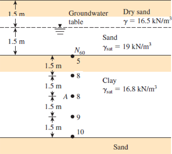
Refer to Figure P3.3. Use Eqs. (3.10) and (3.11) to determine the variation of OCR and preconsolidation pressure
FIGURE P3.3
Expert Solution & Answer

Trending nowThis is a popular solution!

Students have asked these similar questions
1. The following figure shows the stress-displacement results of four direct shear tests
under different vertical stresses.
70
60
o'v=10 psi
50
- o'v=20 psi
40
Δσ'ν-40 psi
o'v=80 psi
30
20
10
0.05
0.1
0.15
0.2
0.25
0.3
shear displ. [in]
Based on the results above, develop the Mohr-Coulomb failure envelope. Indicate the
cohesion (c') and calculate the drained friction angle (o').
shear stress [psi]
Question: A Blasius Exact Solution
Equation For A Laminar Flat-Plate
Boundary Layer Problem Which...
A Blasius exact solution equation for a laminar flat-plate boundary layer problem
which derived from Navier-Stoke equations, could be written as,
ff"-2f"'=0
where f = f(n), =d'fm),
dn?
d'f(n).
df (N) =-
,and f'=-
dn'
dn
U is mainstream fluid velocity and u is fluid velocity in boundary layer.
With suitable boundary conditions, the above equation had been solved by 4th-order
Runge-Kutta numerical integration and the result is tabulated in Table Qla.
TABLE Qla
f'=w/U
f"
7 = y,
VX
0.000
0.000
0.332
0.323
0.267
1
0.166
0.330
0.630
0.846
0.956
0.992
0.998
0.650
1.397
2.310
3.283
0.161
0.064
3
4
0.016
0.002
6
7
4.280
0.001
5.279
6.280
0.999
1.000
0.000
Show that :
CoRe , = 1.27
%3D
A line load of q=60kn/m with alpha =300 is placed on a ground surface as shown in figure p4.1.Calculate the increase of pore water pressure at M immediately after application of the load for the cases given below.
(a) z=10m ,X=0m ,v=0.5 ,A=0.45
(b) z=10m, X=2m,v=0.45, A=0.6
Chapter 3 Solutions
Bundle: Principles Of Foundation Engineering, 9th + Mindtap Engineering, 1 Term (6 Months) Printed Access Card
Ch. 3 - Prob. 3.1PCh. 3 - Prob. 3.2PCh. 3 - Prob. 3.3PCh. 3 - Refer to Figure P3.3. Use Eqs. (3.10) and (3.11)...Ch. 3 - Prob. 3.5PCh. 3 - Prob. 3.6PCh. 3 - Prob. 3.7PCh. 3 - Prob. 3.8PCh. 3 - Prob. 3.9PCh. 3 - Prob. 3.10P
Ch. 3 - Prob. 3.11PCh. 3 - Prob. 3.12PCh. 3 - Prob. 3.13PCh. 3 - Prob. 3.14PCh. 3 - Prob. 3.15PCh. 3 - Prob. 3.16PCh. 3 - Prob. 3.17PCh. 3 - Prob. 3.18PCh. 3 - Prob. 3.19PCh. 3 - Prob. 3.20PCh. 3 - Prob. 3.21PCh. 3 - Prob. 3.22PCh. 3 - Prob. 3.23PCh. 3 - Prob. 3.24PCh. 3 - Prob. 3.25PCh. 3 - Prob. 3.26PCh. 3 - Prob. 3.27PCh. 3 - Prob. 3.28PCh. 3 - Prob. 3.29PCh. 3 - Prob. 3.30PCh. 3 - Prob. 3.31P
Knowledge Booster


Learn more about
Need a deep-dive on the concept behind this application? Look no further. Learn more about this topic, civil-engineering and related others by exploring similar questions and additional content below.Similar questions
- 9.30 A laminar boundary layer velocity profile is approximated by the two straight-line segments indicated in Fig. P9.30. Use the momentum integral equation to determine the boundary layer thickness, 88(x), and wall shear stress, 7, 7(x). Compare these results with those in Table 9.2. 8/2 2U U 3 FIGURE P9.30arrow_forward3.11 An oil storage tank that is circular in plan is to be constructed over a layer of sand, as shown in Figure P3.5. Calculate the following settlements due to the uniformly distributed load g of the storage tank: 9 (a) The elastic settlement below the center of the tank at z = 0 and 3m. (b) The elastic settlement at (i) z = 1.5m, s = 0; (ii) z = 1.5m, s = 3m. Assume that v = 0.3, E = 36MN/m², B = 6m, and q = 145kN/m² Diameter 8- Center line TE Sand Unit weight - Y Poisson's ratio = v Modulus of clasticity = Ez Figure P3.5arrow_forwardUse Eq. (6.14) to determine the stress increase Δσ at z = 10 ft below the center of the area described in Problem 6.5.arrow_forward
- 3. The upward flow of water through a layer of sand in the tank shown in figure has the following properties: e =0.50, G-2.67. Determine the following: a) Effective stress at point A b) Effective stress at point B c) Upward seepage force per unit volume of soil 0.8m 3.5m Supply of Water 0.5m A B 1.9marrow_forwardThe soil profile shown consists of dry sand (4-m thick) which overlies a layer of clay (3-m thick). Ground water table is located at the interface of the sand and clay. a. If the water table rises to the top of the ground surface, what is the change in the effective stress (in kPa) at the bottom of the clay layer? Round off to two decimal places. (ANSWER: 26.336) b. Compute the effective stress at the bottom of the clay layer in kPa. Round off to three decimal places (ANSWER: 97.686) c. How many meters must the ground water table rise to decrease the effective stress by 14 kPa, at the bottom of the clay layer? Round off to two decimal places (ANSWER: 2.13)arrow_forwardProblem 3. The strain rosette shown has angles 0, = 0° (aligned with the x-axis), 0, = 60°, and 0, = 120°, We attach it to a body and then load the body. The strain m m rosette reports the following values: E = 500µ, E, =1200µ, and ɛ. 100µ- m Recall for a delta rosette: Ex = Ea %3D 1 Ey 3 =(26, +26, - 8.) %3D 2 Yy = J a Sketch Mohr's Circle for Strain. Indicate the following Y Max 20,, &,, E2, and- InPlane on your sketch the followinge 2 Determine the following: E2. Op. YMax InPlanearrow_forward
- Question 2 The figure below shows a three-layer system. Calculate the maximum horizontal strain at the bottom of the HMA layer. Layer 1 has a thickness of 11.5 in. E₁= = 400,000 psi E₂ =20,000 psi E3 = 10,000 psi 40,000 lb 150 psi TZTET &₁ = ? &₂ = ? V1 = 0.5 V₂ = 0.5 V3 = 0.5 23 in. 8arrow_forward4.1 A line load of q = 60kN/m with a = 0 is placed on a ground surface as shown in Figure P4.1. Calculate the increase of pore water pressure at M immediately after application of the load for the cases given below. (a) z = 10m, x = 0m, v=0.5, A=0.45. (b) == 10m, x= 2m, v= 0.45, A=0.6. 2 m 4. G.W.T. Clay XI 1arrow_forwardQuestion 4.9 A rock consists of six layers of different permeabilities. The geometry of the rock is given in the figure below. The permeability and dimensions of each layer are given in the table below. a) Find the average permeability of this rock for horizontal flow (k,). b) Find the average permeability of this rock for vertical flow (k). c) What is the k /k,? 1 2 4 6 Layer Permeability [mD] Thickness [in] Length [in] Width [in] 1 50 30 10 2 60 3.5 9. 10 3 30 1.7 21 10 4 40 1.8 21 10 20 2.5 18 10 10 2.5 12 10arrow_forward
- Repeat Problem 10.12 for q = 700 kN/m2, B = 8 m, and z = 4 m. In this case, point A is located below the centerline under the strip load. 10.12 Refer to Figure 10.43. A strip load of q = 1450 lb/ft2 is applied over a width with B = 48 ft. Determine the increase in vertical stress at point A located z = 21 ft below the surface. Given x = 28.8 ft. Figure 10.43arrow_forwardBased on the figure given below, determine the stress increase at Points A, B and C at a depth of 2 m below the ground surface. ←3 m 5 m A 9₁ = 90 kPa B Carrow_forwardQi/ 1- Find the value of h in the piezometer shown in Figure No. (1). 2- Find the value of pressure at the center of water layer. 0.5 m P.=30(KN/m2) h Oil 3.6m G oil =0.82 piezometer 2m Water Fig.(1)arrow_forward
arrow_back_ios
SEE MORE QUESTIONS
arrow_forward_ios
Recommended textbooks for you
 Principles of Foundation Engineering (MindTap Cou...Civil EngineeringISBN:9781337705028Author:Braja M. Das, Nagaratnam SivakuganPublisher:Cengage Learning
 Principles of Geotechnical Engineering (MindTap C...Civil EngineeringISBN:9781305970939Author:Braja M. Das, Khaled SobhanPublisher:Cengage Learning
 Fundamentals of Geotechnical Engineering (MindTap...Civil EngineeringISBN:9781305635180Author:Braja M. Das, Nagaratnam SivakuganPublisher:Cengage Learning
Principles of Foundation Engineering (MindTap Cou...
Civil Engineering
ISBN:9781337705028
Author:Braja M. Das, Nagaratnam Sivakugan
Publisher:Cengage Learning
Principles of Geotechnical Engineering (MindTap C...
Civil Engineering
ISBN:9781305970939
Author:Braja M. Das, Khaled Sobhan
Publisher:Cengage Learning
Fundamentals of Geotechnical Engineering (MindTap...
Civil Engineering
ISBN:9781305635180
Author:Braja M. Das, Nagaratnam Sivakugan
Publisher:Cengage Learning
Understanding Stresses in Beams; Author: The Efficient Engineer;https://www.youtube.com/watch?v=f08Y39UiC-o;License: Standard Youtube License