
Concept explainers
Videos
Determine v1 and v2 in the circuit of Fig. 3.101.
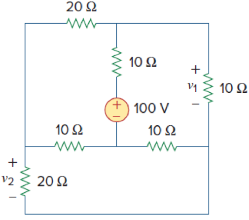
Figure 3.101
For Prob. 3.56.
Find the voltages
Answer to Problem 56P
The value of voltages
Explanation of Solution
Given data:
Refer Figure 3.101 in the textbook for mesh analysis.
Calculation:
Redraw the given circuit as shown in Figure 1 with the mesh currents.
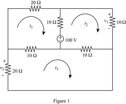
Apply Kirchhoff’s voltage law to loop 1 with current
Apply Kirchhoff’s voltage law to loop 2 with current
Apply Kirchhoff’s voltage law to loop 3 with current
Represent the equations (1), (2), and (3) in matrix form.
Obtain the value of the determinants as follows.
Write the expression for the mesh currents using Cramer’s rule.
Substitute
Substitute
With reference to Figure 1, write the expression for the voltages
Substitute
Substitute
Conclusion:
Therefore, the values of voltage
Want to see more full solutions like this?
Chapter 3 Solutions
EBK FUNDAMENTALS OF ELECTRIC CIRCUITS


- Q3: Obtain the Thevenin equivalent circuits at terminals a-b for the circuit in figure shown below: R, V, I 2002 2% Vo- www 10 (2 3 A a obarrow_forward3.) Please find the differential equation(s) that model the electrical circuit shown in Fig. 3-39 in Ogata (page 99). ei C HH R₁ ww A R₂ ww Figure 3-39 Operational-amplifier circuit. eoarrow_forwardElectrical Engineering Find the voltage V (between terminals a and b). Let R, = 6 2, R, = 3 N, R3 = 2 Q, R4 = 2 N, V, = 10 V, Is= 3 A. ab R2 R1 Is R3 R4 vs solve using superposition and find Vabarrow_forward
- Do a circuit analysis on the diagram 3 using the VIRPE Table: 3. R,=20 V,=12V R3=10 R=40 R;=50 R3=30 R=60arrow_forward3. Use the principle of superposition to calculate "Va", and "N" for the circuit shown below. Please draw each circuit used. a.) How many circuits are necessary to use superposition in this case N= b.) Va = R1 Va R2 2kQ Vs1 10 V vs2 C5 Varrow_forwardFor the following circuit, find vi, V2, and v3. 14 2 k: ww 40 V 15 Q 102arrow_forward
- Define Superposition Theorem with necessary circuit diagram. Explain the steps followed in superposition theorem. n.arrow_forwardQ3. Use superposition method to get the value of Vxarrow_forwardSuperposition theorem does not support calculations of .. .. Power Voltage Current It is working for all: current , voltage and Power.arrow_forward
- Determine R and G in the circuit of Fig.3.51b if the 5A source supplies 100 W, and the 40-V source supplies 500 W.arrow_forwardResistors are said to be connected in parallel when two circuit elements connect at a single node pair. Select one: True False Previous page Nexarrow_forward4- In the circuit in following figure, obtain y 1, v2, and v3. 15 V 25 V 10 V 20 Varrow_forward
 Introductory Circuit Analysis (13th Edition)Electrical EngineeringISBN:9780133923605Author:Robert L. BoylestadPublisher:PEARSON
 Delmar's Standard Textbook Of ElectricityElectrical EngineeringISBN:9781337900348Author:Stephen L. HermanPublisher:Cengage Learning
 Programmable Logic ControllersElectrical EngineeringISBN:9780073373843Author:Frank D. PetruzellaPublisher:McGraw-Hill Education
 Fundamentals of Electric CircuitsElectrical EngineeringISBN:9780078028229Author:Charles K Alexander, Matthew SadikuPublisher:McGraw-Hill Education
 Electric Circuits. (11th Edition)Electrical EngineeringISBN:9780134746968Author:James W. Nilsson, Susan RiedelPublisher:PEARSON
 Engineering ElectromagneticsElectrical EngineeringISBN:9780078028151Author:Hayt, William H. (william Hart), Jr, BUCK, John A.Publisher:Mcgraw-hill Education,