
Concept explainers
Videos
For the transistor circuit shown in Fig. 3.125, find IB and VCE. Let β = 100, and VBE = 0.7 V.
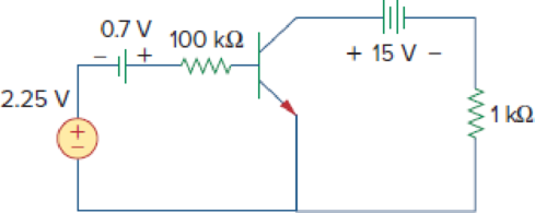
Figure 3.125
Find
Answer to Problem 89P
The value of
Explanation of Solution
Given data:
Refer Figure 3.125 in the textbook for the transistor circuit.
The common-emitter current gain
The base-emitter voltage
Formula used:
Write the expression for collector current in transistor.
Here,
Calculation:
Modify the given figure with the representation of currents and voltages as shown in Figure 1.
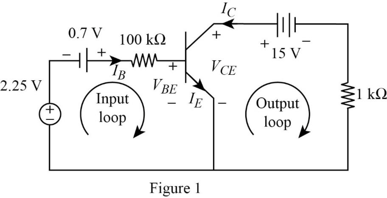
Apply Kirchhoff’s voltage law to input loop in Figure 1.
Substitute
Simplify the equation as follows.
Apply Kirchhoff’s voltage law to output loop in Figure 1.
Substitute equation (1) in (2).
Substitute
Conclusion:
Therefore, the value of
Want to see more full solutions like this?
Chapter 3 Solutions
FUND.OF ELECTRIC CIRCUITS(LL)-W/CONNECT


 Introductory Circuit Analysis (13th Edition)Electrical EngineeringISBN:9780133923605Author:Robert L. BoylestadPublisher:PEARSON
 Delmar's Standard Textbook Of ElectricityElectrical EngineeringISBN:9781337900348Author:Stephen L. HermanPublisher:Cengage Learning
 Programmable Logic ControllersElectrical EngineeringISBN:9780073373843Author:Frank D. PetruzellaPublisher:McGraw-Hill Education
 Fundamentals of Electric CircuitsElectrical EngineeringISBN:9780078028229Author:Charles K Alexander, Matthew SadikuPublisher:McGraw-Hill Education
 Electric Circuits. (11th Edition)Electrical EngineeringISBN:9780134746968Author:James W. Nilsson, Susan RiedelPublisher:PEARSON
 Engineering ElectromagneticsElectrical EngineeringISBN:9780078028151Author:Hayt, William H. (william Hart), Jr, BUCK, John A.Publisher:Mcgraw-hill Education,