Concept explainers
Videos
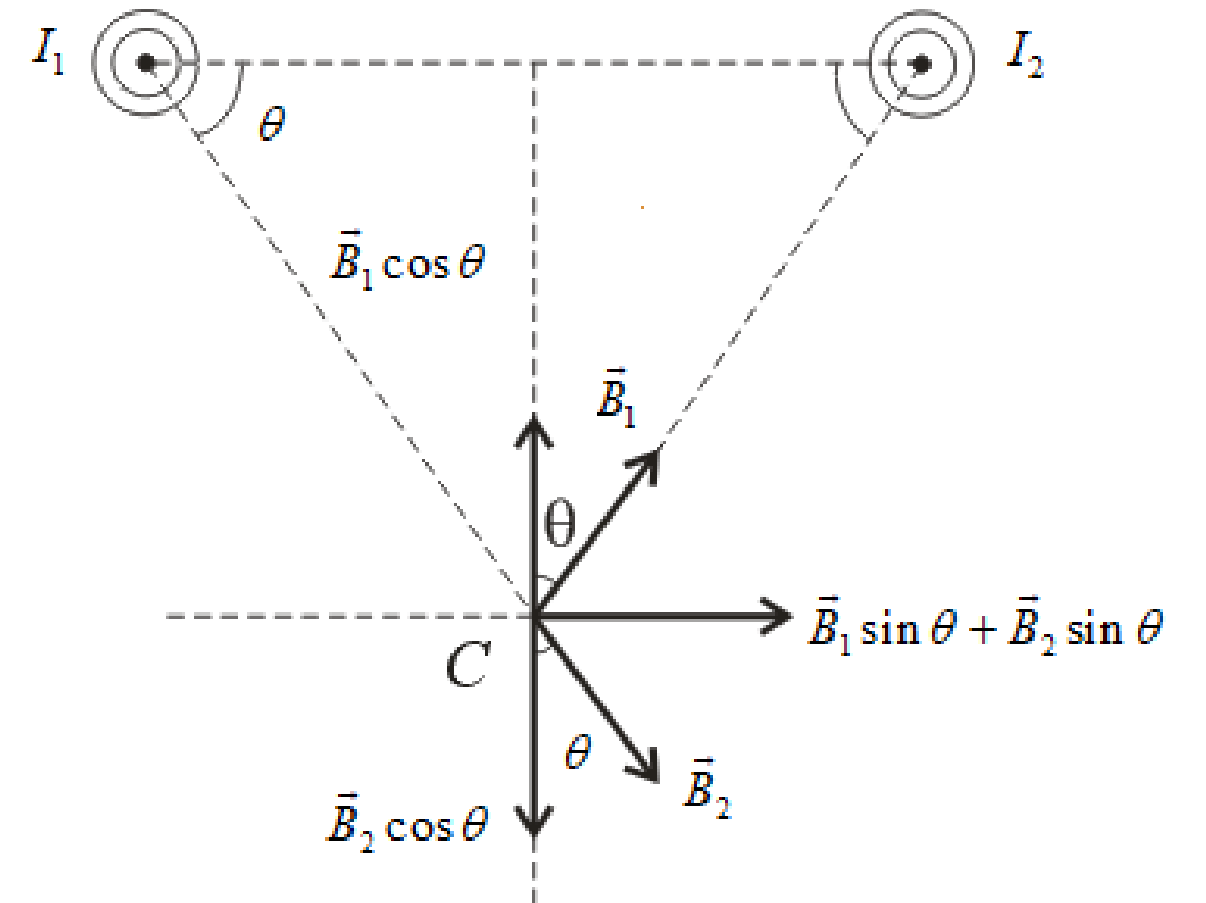
Two long, straight, parallel wires carry current as shown in Figure P30.18. If the currents are equal, find an expression for the magnetic field at point C. Use the indicated coordinate system to write your answer in component form.
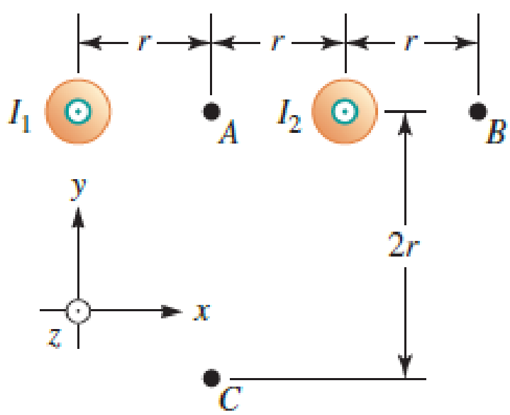
FIGURE P30.18
Find the expression for the magnetic field at point C in component form
Answer to Problem 20PQ
The expression for net magnetic field at point C is
Explanation of Solution
Redraw the figure P30.19 as shown below:
Write the general expression for magnetic field due to wire as.
Here,
The direction of the magnetic field at a point due to a current carrying wire is given by the right hand palm rule.
According to this rule, the thumb of the right hand faces in the direction of the current in the wire, the fingers face towards the point at which magnetic field is to be calculated then the palm faces in the direction of the magnetic field.
The current flowing in the wires is same and the point is at the equal distances from both the wire. Therefore, the vertical components of the magnetic fields will be same for both wires and they will cancel out each other.
Write the expression for the net magnetic field at point C refers to figure (a) above as.
Here,
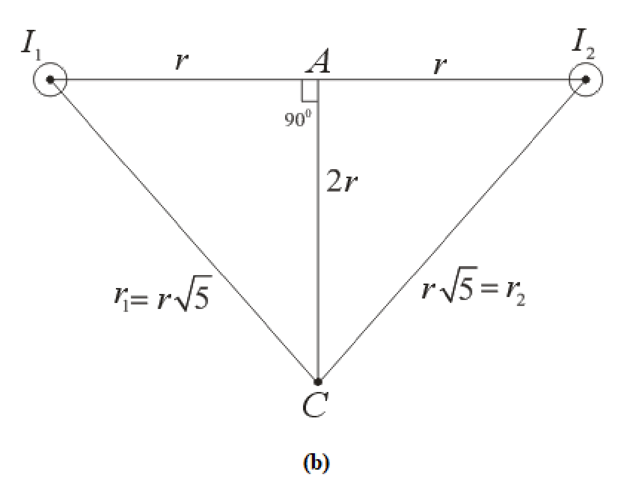
Apply Pythagoras theorem in triangle
Simplify above equation as.
Apply Pythagoras theorem in triangle
Simplify above equation as.
The net magnetic field due to the two wires is in the positive X-direction. The components of the field in the X-direction are calculated as below.
Substitute
Here,
Substitute
Here,
Write the expression for the value of
Substitute
Substitute
Conclusion:
Substitute
Thus, the expression for net magnetic field at point C is
Want to see more full solutions like this?
Chapter 30 Solutions
Student Solutions Manual For Katz's Physics For Scientists And Engineers: Foundations And Connections, Volume 1


- Two long, straight wires carry the same current as shown in Figure P30.22. One wire is parallel to the z axis and the other wire is parallel to the x axis as shown. Find an expression for the magnetic field at the origin.arrow_forwardFigure P30.10 shows a circular current-carrying wire. Using the coordinate system indicated (with the z axis out of the page), state the direction of the magnetic field at points A and B.arrow_forwardTwo infinitely long current-carrying wires run parallel in the xy plane and are each a distance d = 11.0 cm from the y axis (Fig. P30.83). The current in both wires is I = 5.00 A in the negative y direction. a. Draw a sketch of the magnetic field pattern in the xz plane due to the two wires. What is the magnitude of the magnetic field due to the two wires b. at the origin and c. as a function of z along the z axis, at x = y = 0? FIGURE P30.83arrow_forward
- Figure P30.11 shows three configurations of wires and the resultant magnetic fields due to current in the wires. What is the direction of the current that gives the resultant magnetic field shown in each case?arrow_forwardA circular coil 15.0 cm in radius and composed of 145 tightly wound turns carries a current of 2.50 A in the counterclockwise direction, where the plane of the coil makes an angle of 15.0 with the y axis (Fig. P30.73). The coil is free to rotate about the z axis and is placed in a region with a uniform magnetic field given by B=1.35jT. a. What is the magnitude of the magnetic torque on the coil? b. In what direction will the coil rotate? FIGURE P30.73arrow_forwardA metal rod of mass m slides without friction along two parallel horizontal rails, separated by a distance and connected by a resistor R, as shown in Figure P30.13. A uniform vertical magnetic field of magnitude B is applied perpendicular to the plane of the paper. The applied force shown in the figure acts only for a moment, to give the rod a speed v. In terms of m, , R, B, and v, find the distance the rod will then slide as it coasts to a stop. Figure P30.13arrow_forward
- For both sketches in Figure P30.56, there is a 3.54-A current, a magnetic field strength B 0.650 T. and the angle is 32.0. Find the magnetic force per unit length (magnitude and direction) exerted on the current-carrying conductor in both cases.arrow_forwardThe triangular loop of wire shown in Figure P30.62 carries a current of 0.125 A, and a uniform magnetic field of 0.250 T points toward the right. Determine the force on each segment of the wire (indicate magnitude and direction) and the net force on the triangular loop.arrow_forwardA Derive an expression for the magnetic field produced at point P due to the current-carrying wire shown in Figure P30.26. The curved parts of the wire are pieces of concentric circles. Point P is at their center.arrow_forward
- A wire is bent in the form of a square loop with sides of length L (Fig. P30.24). If a steady current I flows in the loop, determine the magnitude of the magnetic field at point P in the center of the square. FIGURE P30.24arrow_forwardA uniform magnetic field B=5.44104iT passes through a closed surface with a slanted top as shown in Figure P31.59. a. Given the dimensions and orientation of the closed surface shown, what is the magnetic flux through the slanted top of the surface? b. What is the net magnetic flux through the entire closed surface?arrow_forwardReview. The bar of mass m in Figure P30.51 is pulled horizontally across parallel, frictionless rails by a massless string that passes over a light, frictionless pulley and is attached to a suspended object of mass M. The uniform upward magnetic field has a magnitude B, and the distance between the rails is . The only significant electrical resistance is the load resistor R shown connecting the rails at one end. Assuming the suspended object is released with the bar at rest at t = 0, derive an expression that gives the bars horizontal speed as a function of time. Figure P30.51arrow_forward
 Physics for Scientists and Engineers: Foundations...PhysicsISBN:9781133939146Author:Katz, Debora M.Publisher:Cengage Learning
 Principles of Physics: A Calculus-Based TextPhysicsISBN:9781133104261Author:Raymond A. Serway, John W. JewettPublisher:Cengage Learning
 Physics for Scientists and EngineersPhysicsISBN:9781337553278Author:Raymond A. Serway, John W. JewettPublisher:Cengage Learning
 Physics for Scientists and Engineers with Modern ...PhysicsISBN:9781337553292Author:Raymond A. Serway, John W. JewettPublisher:Cengage Learning