
Videos
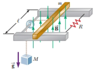
Review. The bar of mass m in Figure P30.51 is pulled horizontally across parallel, frictionless rails by a massless string that passes over a light, frictionless pulley and is attached to a suspended object of mass M. The uniform upward magnetic field has a magnitude B, and the distance between the rails is ℓ. The only significant electrical resistance is the load resistor R shown connecting the rails at one end. Assuming the suspended object is released with the bar at rest at t = 0, derive an expression that gives the bar’s horizontal speed as a function of time.
Figure P30.51
Answer to Problem 51CP
Explanation of Solution
Given info: Mass of bar is
The emf induced in the bar can be given as,
Here,
The current induced in the bar can be given as,
Here,
Substitute
The force induced in the bar due to magnetic field can be given as,
Here,
Substitute
The force due to weight can be given as,
Here,
As, force due to magnetic field and force due to weight will act in opposite direction, the net force acting on the bar can be given by subtracting equation (2) from equation (1),
Here,
The net force can also be given as,
Substitute
The equation (4) is a linear differential equation of the form,
Here,
The integrating factor for the equation (4) can be given as,
Here,
The solution for the differential equation is,
Here,
Substitute
Apply boundary condition,
Substitute
Thus, the expression for speed of the bar is
Conclusion:
Therefore, the expression for horizontal speed of the bar as a function of time will be
Want to see more full solutions like this?
Chapter 30 Solutions
Bundle: Physics for Scientists and Engineers, Volume 2, Loose-leaf Version, 10th + WebAssign Printed Access Card, Single-Term


- A metal rod of mass m slides without friction along two parallel horizontal rails, separated by a distance and connected by a resistor R, as shown in Figure P30.13. A uniform vertical magnetic field of magnitude B is applied perpendicular to the plane of the paper. The applied force shown in the figure acts only for a moment, to give the rod a speed v. In terms of m, , R, B, and v, find the distance the rod will then slide as it coasts to a stop. Figure P30.13arrow_forwardA circular coil 15.0 cm in radius and composed of 145 tightly wound turns carries a current of 2.50 A in the counterclockwise direction, where the plane of the coil makes an angle of 15.0 with the y axis (Fig. P30.73). The coil is free to rotate about the z axis and is placed in a region with a uniform magnetic field given by B=1.35jT. a. What is the magnitude of the magnetic torque on the coil? b. In what direction will the coil rotate? FIGURE P30.73arrow_forwardIn Figure P30.38, the rolling axle, 1.50 m long, is pushed along horizontal rails at a constant speed v = 3.00 m/s. A resistor R = 0.400 is connected to the rails at points a and b, directly opposite each other. The wheels make good electrical contact with the rails, so the axle, rails, and R form a closed-loop circuit. The only significant resistance in the circuit is R. A uniform magnetic field B = 0.080 0 T is vertically downward. (a) Find the induced current I in the resistor. (b) What horizontal force F is required to keep the axle rolling at constant speed? (c) Which end of the resistor, a or b, is at the higher electric potential? (d) What If? After the axle rolls past the resistor, does the current in R reverse direction? Explain your answer. Figure P30.38arrow_forward
- A wire is bent in the form of a square loop with sides of length L (Fig. P30.24). If a steady current I flows in the loop, determine the magnitude of the magnetic field at point P in the center of the square. FIGURE P30.24arrow_forwardA metal rod of mass m slides without friction along two parallel horizontal rails, separated by a distance l and connected by a resistor R, as shown in Figure P23.15. A uniform vertical magnetic field of magnitude B is applied perpendicular to the plane of the paper. The applied force shown in the figure acts only for a moment, to give die rod a speed v. In terms of m, l, R, B, and v, find the distance the rod will then slide as it coasts to a stop.arrow_forwardThree long, current-carrying wires are parallel to one another and separated by a distance d. The magnitudes and directions of the currents are shown in Figure P30.91. Wires 1 and 3 are fixed, but wire 2 is free to move. Wire 2 is displaced to the right by a small distance x. Determine the net force (per unit length) acting on wire 2 and the angular frequency of the resulting oscillation. Assume the mass per unit length of wire 2 is and x d. FIGURE P30.91arrow_forward
- A long solenoid, with its axis along the x axis, consists of 200 turns per meter of wire that carries a steady current of 15.0 A. A coil is formed by wrapping 30 turns of thin wire around a circular frame that has a radius of 8.00 cm. The coil is placed inside the solenoid and mounted on an axis that is a diameter of the coil and coincides with the y axis. The coil is then rotated with an angular speed of 4.00 rad/s. The plane of the coil is in the yz plane at t = 0. Determine the emf generated in the coil as a function of time.arrow_forwardThe homopolar generator, also called the Faraday disk, is a low-voltage, high-current electric generator. It consists of a rotating conducting disk with one stationary brush (a sliding electrical contact) at its axle and another at a point on its circumference as shown in Figure P23.21. A uniform magnetic field is applied perpendicular to the plane of the disk. Assume the field is 0.900 T, the angular speed is 3.20 103 rev/min, and the radius of the disk is 0.400 m. Find the emf generated between the brushes. When superconducting coils are used to produce a large magnetic field, a homopolar generator can have a power output of several megawatts. Such a generator is useful, for example, in purifying metals by electrolysis. If a voltage is applied to the output terminals of the generator, it runs in reverse as a homopolar motor capable of providing great torque, useful in ship propulsion.arrow_forwardA square loop with side length L, mass M, and resistance R lies in the xy plane. A magnetic field B = B0(y/L) k is present in the region of the space near the loop. Determine the magnitude and direction of the induced current in the loop as the loop starts moving at velocity v = B0(y/L) j.arrow_forward
- The triangular loop of wire shown in Figure P30.62 carries a current of 0.125 A, and a uniform magnetic field of 0.250 T points toward the right. Determine the force on each segment of the wire (indicate magnitude and direction) and the net force on the triangular loop.arrow_forwardTwo infinitely long current-carrying wires run parallel in the xy plane and are each a distance d = 11.0 cm from the y axis (Fig. P30.83). The current in both wires is I = 5.00 A in the negative y direction. a. Draw a sketch of the magnetic field pattern in the xz plane due to the two wires. What is the magnitude of the magnetic field due to the two wires b. at the origin and c. as a function of z along the z axis, at x = y = 0? FIGURE P30.83arrow_forwardFor both sketches in Figure P30.56, there is a 3.54-A current, a magnetic field strength B 0.650 T. and the angle is 32.0. Find the magnetic force per unit length (magnitude and direction) exerted on the current-carrying conductor in both cases.arrow_forward
 Physics for Scientists and Engineers with Modern ...PhysicsISBN:9781337553292Author:Raymond A. Serway, John W. JewettPublisher:Cengage Learning
 Physics for Scientists and EngineersPhysicsISBN:9781337553278Author:Raymond A. Serway, John W. JewettPublisher:Cengage Learning
 Principles of Physics: A Calculus-Based TextPhysicsISBN:9781133104261Author:Raymond A. Serway, John W. JewettPublisher:Cengage Learning
 Physics for Scientists and Engineers: Foundations...PhysicsISBN:9781133939146Author:Katz, Debora M.Publisher:Cengage Learning