Videos
(a)
The proof for the statement that the magnetic field on the axis at a distance
(a)
Answer to Problem 60AP
The proof for the statement that the magnetic field at a distance
Explanation of Solution
The following figure shows two circular coils of radius
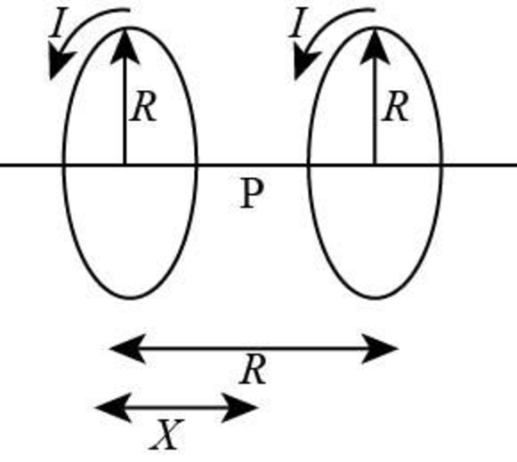
Figure-(1)
From Figure (1) consider that the distance
Write the expression for the magnetic field at point
Here,
Write the expression for the magnetic field at point
Here,
From Figure (1) it is shown that the current is flowing on the same direction. Therefore the expression for the net magnetic field at point
Here,
Substitute
Therefore, magnetic field at a distance
(b)
The proof that
(b)
Answer to Problem 60AP
The proof that
Explanation of Solution
The magnetic field at the point midway between the coils is,
Differentiate the above equation with respect to
Substitute
Differentiate Equation (II) with respect to
Substitute
Further solve the above equation.
Conclusion:
From Equation (III) and Equation (IV),
Therefore, both the coils are Helmholtz coils.
Want to see more full solutions like this?
Chapter 30 Solutions
Physics For Scientists And Engineers With Modern Physics, 9th Edition, The Ohio State University


- A wire is bent in the form of a square loop with sides of length L (Fig. P30.24). If a steady current I flows in the loop, determine the magnitude of the magnetic field at point P in the center of the square. FIGURE P30.24arrow_forwardA metal rod of mass m slides without friction along two parallel horizontal rails, separated by a distance and connected by a resistor R, as shown in Figure P30.13. A uniform vertical magnetic field of magnitude B is applied perpendicular to the plane of the paper. The applied force shown in the figure acts only for a moment, to give the rod a speed v. In terms of m, , R, B, and v, find the distance the rod will then slide as it coasts to a stop. Figure P30.13arrow_forwardIn Figure P30.38, the rolling axle, 1.50 m long, is pushed along horizontal rails at a constant speed v = 3.00 m/s. A resistor R = 0.400 is connected to the rails at points a and b, directly opposite each other. The wheels make good electrical contact with the rails, so the axle, rails, and R form a closed-loop circuit. The only significant resistance in the circuit is R. A uniform magnetic field B = 0.080 0 T is vertically downward. (a) Find the induced current I in the resistor. (b) What horizontal force F is required to keep the axle rolling at constant speed? (c) Which end of the resistor, a or b, is at the higher electric potential? (d) What If? After the axle rolls past the resistor, does the current in R reverse direction? Explain your answer. Figure P30.38arrow_forward
- Two infinitely long current-carrying wires run parallel in the xy plane and are each a distance d = 11.0 cm from the y axis (Fig. P30.83). The current in both wires is I = 5.00 A in the negative y direction. a. Draw a sketch of the magnetic field pattern in the xz plane due to the two wires. What is the magnitude of the magnetic field due to the two wires b. at the origin and c. as a function of z along the z axis, at x = y = 0? FIGURE P30.83arrow_forwardReview. The bar of mass m in Figure P30.51 is pulled horizontally across parallel, frictionless rails by a massless string that passes over a light, frictionless pulley and is attached to a suspended object of mass M. The uniform upward magnetic field has a magnitude B, and the distance between the rails is . The only significant electrical resistance is the load resistor R shown connecting the rails at one end. Assuming the suspended object is released with the bar at rest at t = 0, derive an expression that gives the bars horizontal speed as a function of time. Figure P30.51arrow_forwardWithin the green dashed circle show in Figure P30.21, the magnetic field changes with time according to the expression B = 2.00t3 4.00t2 + 0.800, where B is in teslas, t is in seconds, and R = 2.50 cm. When t = 2.00 s, calculate (a) the magnitude and (b) the direction of the force exerted on an electron located at point P, which is at a distance r = 5.00 cm from the center of the circular field region. (c) At what instant is this force equal to zero? Figure P30.21arrow_forward
- A loop of wire in the shape of a rectangle of width w and length L and a long, straight wire carrying a current I lie on a tabletop as shown in Figure P23.7. (a) Determine the magnetic flux through the loop due to the current I. (b) Suppose the current is changing with time according to I = a + bt, where a and b are constants. Determine the emf that is induced in the loop if b = 10.0 A/s, h = 1.00 cm, w = 10.0 cm, and L = 1.00 m. (c) What is the direction of the induced current in the rectangle? Figure P23.7arrow_forwardThe triangular loop of wire shown in Figure P30.62 carries a current of 0.125 A, and a uniform magnetic field of 0.250 T points toward the right. Determine the force on each segment of the wire (indicate magnitude and direction) and the net force on the triangular loop.arrow_forwardA toroid has a major radius R and a minor radius r and is tightly wound with N turns of wire on a hollow cardboard torus. Figure P31.6 shows half of this toroid, allowing us to see its cross section. If R r, the magnetic field in the region enclosed by the wire is essentially the same as the magnetic field of a solenoid that has been bent into a large circle of radius R. Modeling the field as the uniform field of a long solenoid, show that the inductance of such a toroid is approximately L=120N2r2R Figure P31.6arrow_forward
- A uniform magnetic field B=5.44104iT passes through a closed surface with a slanted top as shown in Figure P31.59. a. Given the dimensions and orientation of the closed surface shown, what is the magnetic flux through the slanted top of the surface? b. What is the net magnetic flux through the entire closed surface?arrow_forwardA long, straight wire carries a current given by I = Imax sin (t + ). The wire lies in the plane of a rectangular coil of N turns of wire as shown in Figure P30.45. The quantities Imax, , and are all constants. Assume Imax = 50.0 A, = 200 s1, N = 100, h = = 5.00 cm, and L = 20.0 cm. Determine the emf induced in the coil by the magnetic field created by the current in the straight wire. Figure P30.45arrow_forwardA long solenoid, with its axis along the x axis, consists of 200 turns per meter of wire that carries a steady current of 15.0 A. A coil is formed by wrapping 30 turns of thin wire around a circular frame that has a radius of 8.00 cm. The coil is placed inside the solenoid and mounted on an axis that is a diameter of the coil and coincides with the y axis. The coil is then rotated with an angular speed of 4.00 rad/s. The plane of the coil is in the yz plane at t = 0. Determine the emf generated in the coil as a function of time.arrow_forward
 Physics for Scientists and Engineers: Foundations...PhysicsISBN:9781133939146Author:Katz, Debora M.Publisher:Cengage Learning
 Principles of Physics: A Calculus-Based TextPhysicsISBN:9781133104261Author:Raymond A. Serway, John W. JewettPublisher:Cengage Learning
 Physics for Scientists and Engineers with Modern ...PhysicsISBN:9781337553292Author:Raymond A. Serway, John W. JewettPublisher:Cengage Learning
 Physics for Scientists and EngineersPhysicsISBN:9781337553278Author:Raymond A. Serway, John W. JewettPublisher:Cengage Learning
 Physics for Scientists and Engineers, Technology ...PhysicsISBN:9781305116399Author:Raymond A. Serway, John W. JewettPublisher:Cengage Learning