
PHYSICS FOR SCI/ENG:STRAT APPR V1 CUSTO
LATEST Edition
ISBN: 9781323786338
Author: Knight
Publisher: Pearson Custom Publishing
expand_more
expand_more
format_list_bulleted
Videos
Textbook Question
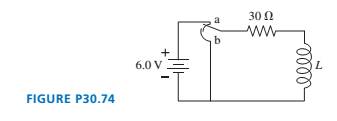
Chapter 30, Problem 74EAP
The inductor in FIGURE P30.74 is a - cm-long, -
 cm- diameter solenoid wrapped with
  turns. What is the current in the circuit
  after the switch is moved from a to b?
Expert Solution & Answer
Want to see the full answer?
Check out a sample textbook solution
Students have asked these similar questions
A 10 -mH inductor and a 25 MF (micro F) capacitor are connected in parallel. The combination is in series with a resistor and a 15 Ohm resistor and 10V, 160Hz emf. (a) What is the current through the resistor? (b) What is the phase angle?
At t = 0, a 12 V battery is connected to a series circuit containing a 10 Ω resistor and a 2.0 H inductor.a) What will be the current in the circuit, a long time after the circuit is established?b) How long will it take the current to reach 50 percent of its final value?
An LC circuit oscillates at a frequency of 10.4 kHz. (a) If the capacitance is 340 mF, what is the inductance? (b) If the maximum current is 7.20 mA, what is the total energy in the circuit? (c)What is the maximum charge on the capacitor?
Chapter 30 Solutions
PHYSICS FOR SCI/ENG:STRAT APPR V1 CUSTO
Ch. 30 - Prob. 1CQCh. 30 - You want to insert a loop of copper wire between...Ch. 30 - A vertical, rectangular loop of copper wire is...Ch. 30 - Does the loop of wire in FIGURE Q30.4 have a...Ch. 30 - s5. The two loops of wire in FIGURE Q30.5 are...Ch. 30 - FIGURE Q30.6 shows a bar magnet being pushed...Ch. 30 - A bar magnet is pushed toward a loop of wire as...Ch. 30 - FIGURE Q30.8 shows a bar magnet. a coil of wire,...Ch. 30 - Prob. 9CQCh. 30 - An inductor with a 2.0 A current stores energy. At...
Ch. 30 - Prob. 11CQCh. 30 - Prob. 12CQCh. 30 - Rank in order, from largest to smallest, the three...Ch. 30 - For the circuit of FIGURE Q30.14: a. What is the...Ch. 30 - The earth’s magnetic field strength is 5.0105T ....Ch. 30 - A potential difference of 0.050 V is developed...Ch. 30 - A 10 -cm-long wire is pulled along a U-shaped...Ch. 30 - What is the magnetic flux through the loop shown...Ch. 30 - FIGURE EX30.5 shows a 10cm10cm square bent at a 90...Ch. 30 - Prob. 6EAPCh. 30 - Prob. 7EAPCh. 30 - FIGURE EX30.8 shows a 2.0 -cm-diameter solenoid...Ch. 30 - Prob. 9EAPCh. 30 - 10. A solenoid is wound as shown in FIGURE...Ch. 30 - 11. The metal equilateral triangle in FIGURE...Ch. 30 - The current in the solenoid of FIGURE EX3O.12 is...Ch. 30 - The loop in FIGURE EX30.13 is being pushed into...Ch. 30 - FIGURE EX30.14 shows a 10-cm-diameter loop in...Ch. 30 - Prob. 15EAPCh. 30 - 16. A -turn coil of wire cm in diameter is in a...Ch. 30 - A 5.0 -cm-diameter coil has 20 turns and a...Ch. 30 - FIGURE EX30.18 shows the current as a function of...Ch. 30 - The magnetic field in FIGURE EX30.19 is decreasing...Ch. 30 - The magnetic field inside a -cm-diameter solenoid...Ch. 30 - Scientists studying an anomalous magnetic field...Ch. 30 - Prob. 22EAPCh. 30 - Prob. 23EAPCh. 30 - Prob. 24EAPCh. 30 - Prob. 25EAPCh. 30 - Prob. 26EAPCh. 30 - How much energy is stored in a -cm-diameter,...Ch. 30 - MRI (magnetic resonance imaging) is a medical...Ch. 30 - Prob. 29EAPCh. 30 - Prob. 30EAPCh. 30 - Prob. 31EAPCh. 30 - Prob. 32EAPCh. 30 - Prob. 33EAPCh. 30 - Prob. 34EAPCh. 30 - At t=0 s, the current in the circuit in FIGURE...Ch. 30 - The switch in FIGURE EX3O.36 has been open for a...Ch. 30 - Prob. 37EAPCh. 30 - Prob. 38EAPCh. 30 - Prob. 39EAPCh. 30 - Prob. 40EAPCh. 30 - A 10cm10cm square loop lies in the xy-plane. The...Ch. 30 - A spherical balloon with a volume of L is in a mT...Ch. 30 - Prob. 43EAPCh. 30 - Prob. 44EAPCh. 30 - Prob. 45EAPCh. 30 - FIGURE P30.46 shows a 4.0-cm-diameter loop with...Ch. 30 - Prob. 47EAPCh. 30 - Prob. 48EAPCh. 30 - Prob. 49EAPCh. 30 - Prob. 50EAPCh. 30 - Prob. 51EAPCh. 30 - Prob. 52EAPCh. 30 - Prob. 53EAPCh. 30 - Prob. 54EAPCh. 30 - Prob. 55EAPCh. 30 - Your camping buddy has an idea for a light to go...Ch. 30 - 57. The -wide, zero-resistance slide wire shown...Ch. 30 - ]58. You’ve decided to make the magnetic...Ch. 30 - FIGURE P30.59 shows a U-shaped conducting rail...Ch. 30 - Prob. 60EAPCh. 30 - Prob. 61EAPCh. 30 - Prob. 62EAPCh. 30 - Equation 30.26 is an expression for the induced...Ch. 30 - Prob. 64EAPCh. 30 - One possible concern with MRI (see Exercise 28) is...Ch. 30 - FIGURE P30.66 shows the current through a 10mH...Ch. 30 - Prob. 67EAPCh. 30 - Prob. 68EAPCh. 30 - Prob. 69EAPCh. 30 - Prob. 70EAPCh. 30 - An LC circuit is built with a inductor and an...Ch. 30 - Prob. 72EAPCh. 30 - For your final exam in electronics, you’re asked...Ch. 30 - The inductor in FIGURE P30.74 is a -cm-long, -cm-...Ch. 30 - The capacitor in FIGURE P30.75 is initially...Ch. 30 - The switch in FIGURE P30.76 has been open for a...Ch. 30 - 77. The switch in FIGURE P30.77 has been open for...Ch. 30 - Prob. 78EAPCh. 30 - Prob. 79EAPCh. 30 - Prob. 80EAPCh. 30 - In recent years it has been possible to buy a 1.0F...Ch. 30 - Prob. 82EAPCh. 30 - Prob. 83EAPCh. 30 - Prob. 84EAPCh. 30 - A 2.0 -cm-diameter solenoid is wrapped with 1000...Ch. 30 - High-frequency signals are often transmitted along...
Knowledge Booster


Learn more about
Need a deep-dive on the concept behind this application? Look no further. Learn more about this topic, physics and related others by exploring similar questions and additional content below.Similar questions
- Two coaxial cables of length with radii a and b are carrying currents in opposite directions as shown in Figure P33.78. Determine the inductance of the system. Hint: Use Ampres law to write an expression for the magnetic field in the region between the cables, a distance r from the axis of the cables. Then calculate the magnetic flux through a narrow rectangular region between the cables such that the Field is perpendicular to the area everywhere. FIGURE P33.78arrow_forwardAn instrument based on induced emf has been used to measure projectile speeds up to 6 km/s. A small magnet is imbedded in the projectile as shown in Figure P23.2. The projectile passes through two coils separated by a distance d. As the projectile passes through each coil, a pulse of emf is induced in the coil. The time interval between pulses can be measured accurately with an oscilloscope, and thus the speed can be determined. (a) Sketch a graph of V versus t for the arrangement shown. Consider a current that flows counterclockwise as viewed from the starting point of the projectile as positive. On your graph, indicate which pulse is from coil 1 and which is from coil 2. (b) If the pulse separation is 2.40 ms and d = 1.50 m, what is the projectile speed? Figure P23.2arrow_forwardThe magnetic field through a square loop of wire with sides of length 3.00 cm changes with time as shown in Figure P32.8, where the sign indicates the direction of the field relative to the axis of the loop. Plot the emf induced in the loop versus time. FIGURE P32.8arrow_forward
- A bar magnet is dropped through a loop of wire as shown in Figure P32.64. a. What is the direction of the induced current as the magnet is approaching the loop, as viewed from above where the magnet begins? b. What is the direction of the induced current after the magnet falls through and is receding from the loop, as viewed from above where the magnet began? FIGURE P32.64arrow_forwardEach of the three situations in Figure P32.68 shows a resistor in a circuit in which currents are induced. Using Lenzs law, determine whether the current in each situation is from a to b or from b to a. a. If the current I in the wire in Figure P32.68A is increased from zero to I, what is the direction of the current induced across the resistor R? b. The switch in Figure P32.68B is initially closed and is thrown open at t = 0. What is the direction of the current induced across the resistor R immediately afterward? c. A bar magnet is brought close to the circuit shown in Figure P32.68C. What is the direction of the current induced across the resistor R?arrow_forwardA coil with a self-inductance of 3.0 H and a resistance of 100 2 carries a steady current of 2.0 A. (a) What is the energy stored in the magnetic field of the coil? (b) What is the energy per second dissipated in the resistance of the coil?arrow_forward
- When a wire carries an AC current with a known frequency, you can use a Rogowski coil to determine the amplitude Imax of the current without disconnecting the wire to shunt the current through a meter. The Rogowski coil, shown in Figure P23.8, simply clips around the wire. It consists of a toroidal conductor wrapped around a circular return cord. Let n represent the number of turns in the toroid per unit distance along it. Let A represent the cross-sectional area of the toroid. Let I(t) = Imax sin t represent the current to be measured. (a) Show that the amplitude of the emf induced in the Rogowski coil is Emax=0nAImax. (b) Explain why the wire carrying the unknown current need not be at the center of the Rogowski coil and why the coil will not respond to nearby currents that it does not enclose. Figure P23.8arrow_forwardA rectangular loop of dimensions and w moves with a constant velocity v away from a long wire that carries a current I in the plane of the loop (Fig. P.10.46). The total resistance of the loop is R. Derive an expression that gives the current in the loop at the instant the near side is a distance r from the wire. Figure P30.46arrow_forwardA) What is the maximum current through the inductor? B) What is the first time at which the current is maximum?arrow_forward
- A 15.00 µF capacitor, labeled as C below, is charged to 175.0 µC at time t = 0. At t = 0, the capacitor is connected across the ends of a 5.00 mH inductor represented by symbol L. The diagram below shows the system just after the fully charged capacitor C is connected to inductor L. The current I just begins to flow at t = 0, reducing the charge Q on the right plate. (a) What is the angular frequency ω of the charge oscillations in the capacitor after the above connection is made? (b) Find the maximum current IMAX. (c) What is the value of charge Q on the right plate when the current I reaches the maximum value IMAX?arrow_forwardVP30.10.3 The sum of the electrical and magnetic energies in an L-C circuit is 0.800 J. At a certain instant the energy is exactly half electrical and half magnetic, the capacitor charge is 5.30 mC, and the current is 8.00 A. Find (a) the capacitance, (b) the inductance, and (c) the angular frequency of oscillation.arrow_forwardA solenoid with a length of 10.0cm has 500 turns and a radius of .01cm. a) What is the self inductance L for this solenoid? b) How much energy is stored in the solenoid if it has a current of 10.0A running through it?arrow_forward
arrow_back_ios
SEE MORE QUESTIONS
arrow_forward_ios
Recommended textbooks for you
 Principles of Physics: A Calculus-Based TextPhysicsISBN:9781133104261Author:Raymond A. Serway, John W. JewettPublisher:Cengage Learning
 Physics for Scientists and Engineers: Foundations...PhysicsISBN:9781133939146Author:Katz, Debora M.Publisher:Cengage Learning
 Physics for Scientists and Engineers with Modern ...PhysicsISBN:9781337553292Author:Raymond A. Serway, John W. JewettPublisher:Cengage Learning
 Physics for Scientists and EngineersPhysicsISBN:9781337553278Author:Raymond A. Serway, John W. JewettPublisher:Cengage Learning
Principles of Physics: A Calculus-Based Text
Physics
ISBN:9781133104261
Author:Raymond A. Serway, John W. Jewett
Publisher:Cengage Learning
Physics for Scientists and Engineers: Foundations...
Physics
ISBN:9781133939146
Author:Katz, Debora M.
Publisher:Cengage Learning
Physics for Scientists and Engineers with Modern ...
Physics
ISBN:9781337553292
Author:Raymond A. Serway, John W. Jewett
Publisher:Cengage Learning
Physics for Scientists and Engineers
Physics
ISBN:9781337553278
Author:Raymond A. Serway, John W. Jewett
Publisher:Cengage Learning
What is Electromagnetic Induction? | Faraday's Laws and Lenz Law | iKen | iKen Edu | iKen App; Author: Iken Edu;https://www.youtube.com/watch?v=3HyORmBip-w;License: Standard YouTube License, CC-BY