
PHYSICS FOR SCIENTISTS & ENGINEERS PKG
LATEST Edition
ISBN: 9781323572917
Author: Knight
Publisher: Pearson Custom Publishing
expand_more
expand_more
format_list_bulleted
Videos
Textbook Question
Chapter 30, Problem 75EAP
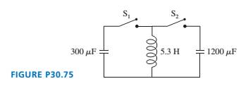
The  capacitor in FIGURE P30.75 is initially charged to ,
  the
the  capacitor is uncharged, and the switches are both open.
a. What is the maximum voltage to which you can charge the  capacitor by the proper closing and opening of the two switches?
b. How would you do it? Describe the sequence in which you would close and open switches and the times at which you would do so. The first switch is closed at . 
Expert Solution & Answer
Want to see the full answer?
Check out a sample textbook solution
Students have asked these similar questions
I’m not certain what to do next in the attached question. If the switch is closed, that means that the capacitor starts discharging, right? I’m just confused on whether there would be current flowing through the capacitor if the switch is closed. Wouldn’t there be a break in the current since the capacitor doesn’t touch? Any help would be appreciated. I just need help understanding C in the question. Thank you!
The switch given has been closed for a very long time.a. What is the charge on the capacitor?b. The switch is opened at t = 0 s. At what time has the charge on the capacitor decreased to 10% of its initial value?
In the figure, the capacitor is initially charged when switch 1 is open and switch 2 is closed. Switch 2 is then opened, and removing the battery from circuit, and the capacitor remains charged. Switch 1 is then closed, so that the capacitor is connected directly across the inductor. A) Find the frequency of oscillation of the circuit. B) What are the maximum values of charge on the capacitor and current in the circuit? C) Determine the charge and current as a functions of time.
Chapter 30 Solutions
PHYSICS FOR SCIENTISTS & ENGINEERS PKG
Ch. 30 - Prob. 1CQCh. 30 - You want to insert a loop of copper wire between...Ch. 30 - A vertical, rectangular loop of copper wire is...Ch. 30 - Does the loop of wire in FIGURE Q30.4 have a...Ch. 30 - s5. The two loops of wire in FIGURE Q30.5 are...Ch. 30 - FIGURE Q30.6 shows a bar magnet being pushed...Ch. 30 - A bar magnet is pushed toward a loop of wire as...Ch. 30 - FIGURE Q30.8 shows a bar magnet. a coil of wire,...Ch. 30 - Prob. 9CQCh. 30 - An inductor with a 2.0 A current stores energy. At...
Ch. 30 - Prob. 11CQCh. 30 - Prob. 12CQCh. 30 - Rank in order, from largest to smallest, the three...Ch. 30 - For the circuit of FIGURE Q30.14: a. What is the...Ch. 30 - The earth’s magnetic field strength is 5.0105T ....Ch. 30 - A potential difference of 0.050 V is developed...Ch. 30 - A 10 -cm-long wire is pulled along a U-shaped...Ch. 30 - What is the magnetic flux through the loop shown...Ch. 30 - FIGURE EX30.5 shows a 10cm10cm square bent at a 90...Ch. 30 - Prob. 6EAPCh. 30 - Prob. 7EAPCh. 30 - FIGURE EX30.8 shows a 2.0 -cm-diameter solenoid...Ch. 30 - Prob. 9EAPCh. 30 - 10. A solenoid is wound as shown in FIGURE...Ch. 30 - 11. The metal equilateral triangle in FIGURE...Ch. 30 - The current in the solenoid of FIGURE EX3O.12 is...Ch. 30 - The loop in FIGURE EX30.13 is being pushed into...Ch. 30 - FIGURE EX30.14 shows a 10-cm-diameter loop in...Ch. 30 - Prob. 15EAPCh. 30 - 16. A -turn coil of wire cm in diameter is in a...Ch. 30 - A 5.0 -cm-diameter coil has 20 turns and a...Ch. 30 - FIGURE EX30.18 shows the current as a function of...Ch. 30 - The magnetic field in FIGURE EX30.19 is decreasing...Ch. 30 - The magnetic field inside a -cm-diameter solenoid...Ch. 30 - Scientists studying an anomalous magnetic field...Ch. 30 - Prob. 22EAPCh. 30 - Prob. 23EAPCh. 30 - Prob. 24EAPCh. 30 - Prob. 25EAPCh. 30 - Prob. 26EAPCh. 30 - How much energy is stored in a -cm-diameter,...Ch. 30 - MRI (magnetic resonance imaging) is a medical...Ch. 30 - Prob. 29EAPCh. 30 - Prob. 30EAPCh. 30 - Prob. 31EAPCh. 30 - Prob. 32EAPCh. 30 - Prob. 33EAPCh. 30 - Prob. 34EAPCh. 30 - At t=0 s, the current in the circuit in FIGURE...Ch. 30 - The switch in FIGURE EX3O.36 has been open for a...Ch. 30 - Prob. 37EAPCh. 30 - Prob. 38EAPCh. 30 - Prob. 39EAPCh. 30 - Prob. 40EAPCh. 30 - A 10cm10cm square loop lies in the xy-plane. The...Ch. 30 - A spherical balloon with a volume of L is in a mT...Ch. 30 - Prob. 43EAPCh. 30 - Prob. 44EAPCh. 30 - Prob. 45EAPCh. 30 - FIGURE P30.46 shows a 4.0-cm-diameter loop with...Ch. 30 - Prob. 47EAPCh. 30 - Prob. 48EAPCh. 30 - Prob. 49EAPCh. 30 - Prob. 50EAPCh. 30 - Prob. 51EAPCh. 30 - Prob. 52EAPCh. 30 - Prob. 53EAPCh. 30 - Prob. 54EAPCh. 30 - Prob. 55EAPCh. 30 - Your camping buddy has an idea for a light to go...Ch. 30 - 57. The -wide, zero-resistance slide wire shown...Ch. 30 - ]58. You’ve decided to make the magnetic...Ch. 30 - FIGURE P30.59 shows a U-shaped conducting rail...Ch. 30 - Prob. 60EAPCh. 30 - Prob. 61EAPCh. 30 - Prob. 62EAPCh. 30 - Equation 30.26 is an expression for the induced...Ch. 30 - Prob. 64EAPCh. 30 - One possible concern with MRI (see Exercise 28) is...Ch. 30 - FIGURE P30.66 shows the current through a 10mH...Ch. 30 - Prob. 67EAPCh. 30 - Prob. 68EAPCh. 30 - Prob. 69EAPCh. 30 - Prob. 70EAPCh. 30 - An LC circuit is built with a inductor and an...Ch. 30 - Prob. 72EAPCh. 30 - For your final exam in electronics, you’re asked...Ch. 30 - The inductor in FIGURE P30.74 is a -cm-long, -cm-...Ch. 30 - The capacitor in FIGURE P30.75 is initially...Ch. 30 - The switch in FIGURE P30.76 has been open for a...Ch. 30 - 77. The switch in FIGURE P30.77 has been open for...Ch. 30 - Prob. 78EAPCh. 30 - Prob. 79EAPCh. 30 - Prob. 80EAPCh. 30 - In recent years it has been possible to buy a 1.0F...Ch. 30 - Prob. 82EAPCh. 30 - Prob. 83EAPCh. 30 - Prob. 84EAPCh. 30 - A 2.0 -cm-diameter solenoid is wrapped with 1000...Ch. 30 - High-frequency signals are often transmitted along...
Knowledge Booster


Learn more about
Need a deep-dive on the concept behind this application? Look no further. Learn more about this topic, physics and related others by exploring similar questions and additional content below.Similar questions
- A 100-mH inductor is connected across the emf of the preceding problem. (a) What is the reactance of the Inductor? (b) Write an expression for the current through the inductor.arrow_forwardIn the high-voltage circuit of the X-ray generator, a transformer is used to supply a 40000 V to machine with power from a 180 V wall plug. The x ray machine operates at 120000 W of power for the production of X-rays. (a) What is the current in the secondary coil of the transformer in ampere? (b) What is the current in the primary coil in ampere? (c) What is the ratio of the number of secondary to primary turns? (d) What type of transformer is this transformerarrow_forwardAn ideal transformer has 600 turns on its primary side and 100 turns on its secondary side. The primary voltage is 1000 V AC a. What will the secondary voltage be with this configuration? b. What is the secondary current if the primary current is 100 A?arrow_forward
- a) What is Ampere’s law. Explain with the help of equationarrow_forwardA) What is the maximum current through the inductor? B) What is the first time at which the current is maximum?arrow_forwardThe switch in Figure P27.51a closes when Vc23Vand opens when Vc13V. The ideal voltmeter reads a potential difference as plotted in Figure P27.51b. What is the period T of the waveform in terms of R1, R2, and C? Figure P27.51arrow_forward
- Each of the three situations in Figure P32.68 shows a resistor in a circuit in which currents are induced. Using Lenzs law, determine whether the current in each situation is from a to b or from b to a. a. If the current I in the wire in Figure P32.68A is increased from zero to I, what is the direction of the current induced across the resistor R? b. The switch in Figure P32.68B is initially closed and is thrown open at t = 0. What is the direction of the current induced across the resistor R immediately afterward? c. A bar magnet is brought close to the circuit shown in Figure P32.68C. What is the direction of the current induced across the resistor R?arrow_forwardIn the figure below, the capacitor is initially uncharged. What is the value of the current (in A) the moment after the switch is closed?arrow_forwardAn alternating current generator in the United Kingdom generates current with a frequency of 50 Hz. Suppose that initially, the current is at its maximum of 12 amperes. If the current varies in simple harmonic motion over time, write a model for the current I (in amperes) as a function of the time t (in seconds).arrow_forward
- (a) A 50mW laser produces a polarized beam of 600nm light. If this laser light is reflected normally off a perfect mirror, then what is the net force of the radiation on the mirror?(b) At t=0 an 80µF capacitor is given a charge of 200µC and is connected across a 50mH inductor. What is the earliest time when the current is its maximum value (just the magnitude) and what is that maximum value?(d) After how many time constants has a discharging capacitor lost 95% of its charge?arrow_forwardA Transformer has 400 primary turns and 1800 secondary turns. The input voltage is 24V and the output current is 4A when connected across a load. a. What is the output voltage of the transformer? b. What is the resistance of the load? c. How much power is dissipated by the resistor?arrow_forwardExamine the circuit drawn in the image below. When the switch is closed assume a very strong magnetic field is produced in the solenoid. ( This solenoid is the typical demonstration solenoid connected to a battery that has a copper ring which can move on the iron core of the solenoid) a) Explain what will happen to the copper ring ( which is free to move when the switch is closed)? b) Explain what will happened to the copper ring when a steady current flows in the circuit? c) Explain what will happen to the copper ring when the switch is opened? d) How would you answers change if terminal on the power supply are reversed? Explain your results.arrow_forward
arrow_back_ios
arrow_forward_ios
Recommended textbooks for you
 Physics for Scientists and Engineers, Technology ...PhysicsISBN:9781305116399Author:Raymond A. Serway, John W. JewettPublisher:Cengage Learning
 Physics for Scientists and Engineers with Modern ...PhysicsISBN:9781337553292Author:Raymond A. Serway, John W. JewettPublisher:Cengage Learning
 Physics for Scientists and EngineersPhysicsISBN:9781337553278Author:Raymond A. Serway, John W. JewettPublisher:Cengage Learning
 Physics for Scientists and Engineers: Foundations...PhysicsISBN:9781133939146Author:Katz, Debora M.Publisher:Cengage Learning
Physics for Scientists and Engineers, Technology ...
Physics
ISBN:9781305116399
Author:Raymond A. Serway, John W. Jewett
Publisher:Cengage Learning
Physics for Scientists and Engineers with Modern ...
Physics
ISBN:9781337553292
Author:Raymond A. Serway, John W. Jewett
Publisher:Cengage Learning
Physics for Scientists and Engineers
Physics
ISBN:9781337553278
Author:Raymond A. Serway, John W. Jewett
Publisher:Cengage Learning
Physics for Scientists and Engineers: Foundations...
Physics
ISBN:9781133939146
Author:Katz, Debora M.
Publisher:Cengage Learning
What is Electromagnetic Induction? | Faraday's Laws and Lenz Law | iKen | iKen Edu | iKen App; Author: Iken Edu;https://www.youtube.com/watch?v=3HyORmBip-w;License: Standard YouTube License, CC-BY