
Videos
Review Suppose you want to use a small, positively charged ball suspended by a light thread to map out the electric field in the space around a charged source. Describe the reaction of the ball as you place it at the two locations in front of the infinitely large, positively charged sheet shown in Figure P31.2A. Be sure to relate your description to what you know about the sheet’s electric field.
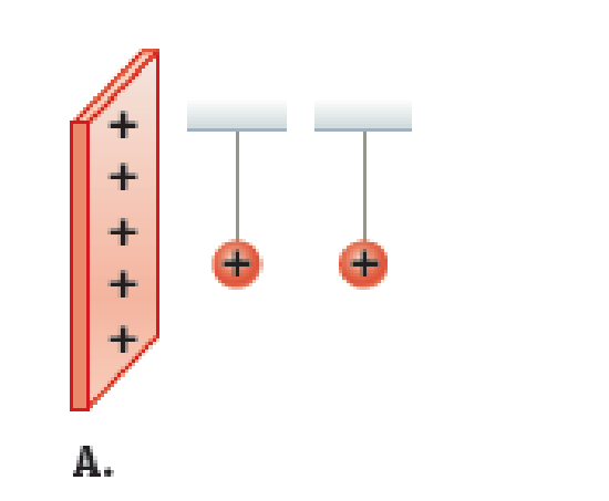
The reaction of the ball at the two different locations.
Answer to Problem 2PQ
The ball will deflect same in both the cases.
Explanation of Solution
Write the expression for the electric field due to a infinite sheet of charge as.
Here,
Write the expression for the force on the positively charged ball as.
Here,
Conclusion:
The ball is of the same charge as of the sheet. So, there will be repulsion of ball and ball will deflect away from the sheet.
Substitute
The electric field at the point nearer to the sheet will be same as the electric field at the point away from the sheet as it is independent of the distance of the charged ball from the sheet.
Thus, the ball will deflect same in both the cases.
Want to see more full solutions like this?
Chapter 31 Solutions
Physics for Scientists and Engineers: Foundations and Connections


- A When we find the electric field due to a continuous charge distribution, we imagine slicing that source up into small pieces, finding the electric field produced by the pieces, and then integrating to find the electric field. Lets see what happens if we break a finite rod up into a small number of finite particles. Figure P24.77 shows a rod of length 2 carrying a uniform charge Q modeled as two particles of charge Q/2. The particles are at the ends of the rod. Find an expression for the electric field at point A located a distance above the midpoint of the rod using each of two methods: a. modeling the rod with just two particles and b. using the exact expression E=kQy12+y2 c. Compare your results to the exact expression for the rod by finding the ratio of the approximate expression to the exact expression. FIGURE P24.77 Problems 77 and 78.arrow_forwardA very long, thin wire fixed along the x axis has a linear charge density of 3.2 C/m. a. Determine the electric field at point P a distance of 0.50 m from the wire. b. If there is a test charge q0 = 12.0 C at point P, what is the magnitude of the net force on this charge? In which direction will the test charge accelerate?arrow_forwardA We saw in Figure 23.16 that a neutral metal can was attracted to a positively charged glass rod because the rod polarized the can. Lets model this situation in a very rough sense. Suppose a charged sphere C is held near two other charged spheres A and B as shown in Figure P23.62. Lets call the magnitude of the electrostatic force exerted by sphere C on A FA and that on B FB. Derive an expression for the ratio FA/FB. Comment on why a neutral conductor is attracted to a charged object. Figure P23.62arrow_forward
- A charged rod is curved so that it is part of a circle of radius R (Fig. P24.32). The excess positive charge Q is uniformly distributed on the rod. Find an expression for the electric field at point A in the plane of the curved rod in terms of the parameters given in the figure.arrow_forwardA uniformly charged rod of length L and total charge Q lies along the x axis as shown in Figure P23.6. (a) Find the components of the electric field at the point P on the y axis a distance d from the origin. (b) What are the approximate values of the field components when d L? Explain why you would expect these results. Figure P23.6arrow_forwardA Find an expression for the position y (along the positive axis perpendicular to the ring and passing through its center) where the electric field due to a charged ring is a maximum. Also find an expression for the electric field at that point.arrow_forward
- Given the arrangement of charged particles in Figure P23.38, find the net electrostatic force on the 10.33-C charged particle.arrow_forwardReview. A block having mass m and charge + Q is connected to an insulating spring having a force constant k. The block lies on a frictionless, insulating, horizontal track, and the system is immersed in a uniform electric field of magnitude E directed as shown in Figure P24.6. The block is released from rest when the spring is unstretched (at x = 0). We wish to show that the ensuing motion of the block is simple harmonic. (a) Consider the system of the block, the spring, and the electric field. Is this system isolated or nonisolated? (b) What kinds of potential energy exist within this system? (c) Call the initial configuration of the system that existing just as the block is released from rest. The final configuration is when the block momentarily comes to rest again. What is the value of x when the block comes to rest momentarily? (d) At some value of x we will call x = x0, the block has zero net force on it. What analysis model describes the particle in this situation? (c) What is the value of x0? (f) Define a new coordinate system x such that x = x x0. Show that x satisfies a differential equation for simple harmonic motion. (g) Find the period of the simple harmonic motion. (h) How does the period depend on the electric field magnitude? Figure P24.6arrow_forwardAn electron is in a uniform upward-pointing electric field. a. If the electron experiences a downward acceleration of 9.81 m/s2, what is the magnitude of the electric field? (Ignore gravity.) b. What is the gravitational force on this electron? Is it okay to ignore gravity? Explain.arrow_forward
- One end of a light spring with force constant k = 125 N/m is attached to a wall, and the other end to a metal block with charge qA = 2.00 C on a horizontal, frictionless table (Fig. P23.34). A second block with charge qB = 3.60 C is brought close to the first block. The spring stretches as the blocks attract each other so that at equilibrium, the blocks are separated by a distance d = 12.0 cm. What is the displacement x of the spring? Figure P23.34arrow_forward6. S Four point charges are at the corners of a square of side a as shown in Figure P15.6. Determine the magnitude and direction of the resultant electric force on q, 24 a with k, q, and a left in symbolic 24 34 form. a 30. Three charges are at the corners of an equilateral triangle, as shown in Figure P15.30. Calculate the electric field at a point midway between the two charges on the x-axis. 3.00 µC 0.500 m 60.0° 60.0% 8.00 µC -5.00 µC Figure P15.30 8. Calculate the magnitude and direction of the Cou- lomb force on each of the three charges shown in Figure P15.8. 6.00 μC 1.50 μC -2.00 µC 3.00 cm + 2.00 cm Figure P15.8arrow_forwardYou are working on a research project in which you must control the direction of travel of electrons using deflection plates. You have devised the apparatus shown. The plates are of length ℓ = 0.500 m and are separated by a distance d = 3.00 cm. Electrons are fired at υi = 5.00 x 10⁶ m/s into a uniform electric field from the left edge of the lower, positive plate, aimed directly at the right edge of the upper, negative plate. Therefore, if there is no electric field between the plates, the electrons will follow the broken line in the figure. With an electric field existing between the plates, the electrons will follow a curved path, bending downward. You need to determine (a) the range of angles over which the electron can leave the apparatus and (b) the electric field required to give the maximum possible deviation angle.arrow_forward
 Physics for Scientists and Engineers: Foundations...PhysicsISBN:9781133939146Author:Katz, Debora M.Publisher:Cengage Learning
 Physics for Scientists and Engineers with Modern ...PhysicsISBN:9781337553292Author:Raymond A. Serway, John W. JewettPublisher:Cengage Learning