Videos
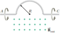
In Figure P30.26, a semicircular conductor of radius R = 0.250 m is rotated about the axis AC at a constant rate of 120 rev/min. A uniform magnetic field of magnitude 1.30 T fills the entire region below the axis and is directed out of the page. (a) Calculate the maximum value of the emf induced between the ends of the conductor. (b) What is the value of the average induced emf for each complete rotation? (c) What If? How would your answers to parts (a) and (b) change if the magnetic field were allowed to extend a distance R above the axis of rotation? Sketch the emf versus time (d) when the field is as drawn in Figure P30.26 and (e) when the field is extended as described in part (c).
Figure P30.26

Trending nowThis is a popular solution!

Chapter 31 Solutions
Physics for Scientists and Engineers, Volume 1


- Figure P23.58 is a graph of the induced emf versus time for a coil of N turns rotating with angular speed ω in a uniform magnetic field directed perpendicular to the coil’s axis of rotation. What If? Copy this sketch (on a larger scale) and on the same set of axes show the graph of emf versus t (a) if the number of turns in the coil is doubled, (b) if instead the angular speed is doubled, and (c) if the angular speed is doubled while the number of turns in the coil is halved. Figure P23.58arrow_forwardA coil with a self-inductance of 3.0 H and a resistance of 100 2 carries a steady current of 2.0 A. (a) What is the energy stored in the magnetic field of the coil? (b) What is the energy per second dissipated in the resistance of the coil?arrow_forwardThe magnetic field through a square loop of wire with sides of length 3.00 cm changes with time as shown in Figure P32.8, where the sign indicates the direction of the field relative to the axis of the loop. Plot the emf induced in the loop versus time. FIGURE P32.8arrow_forward
- A circular loop of wire with a radius of 4.0 cm is in a uniform magnetic field of magnitude 0.060 T. The plane of the loop is perpendicular to the direction of the magnetic field. In a time interval of 0.50 s, the magnetic field changes to the opposite direction with a magnitude of 0.040 T. What is the magnitude of the average emf induced in the loop? (a) 0.20 V (b) 0.025 V (c) 5.0 mV (d) 1.0 mV (e) 0.20 mVarrow_forwardA Figure P32.74 shows an N-turn rectangular coil of length a and width b entering a region of uniform magnetic field of magnitude Bout directed out of the page. The velocity of the coil is constant and is upward in the figure. The total resistance of the coil is R. What are the magnitude and direction of the magnetic force on the coil a. when only a portion of the coil has entered the region with the field, b. when the coil is completely embedded in the field, and c. as the coil begins to exit the region with the field?arrow_forwardFigure P30.39 shows a stationary conductor whose shape is similar to the letter e. The radius of its circular portion is a = 50.0 cm. It is placed in a constant magnetic field of 0.500 T directed out of the page. A straight conducting rod, 50.0 cm long, is pivoted about point O and rotates with a constant angular speed of 2.00 rad/s. (a) Determine the induced emf in the loop POQ. Note that the area of the loop is a2/2. (b) If all the conducting material has a resistance per length of 5.00 /m, what is the induced current in the loop POQ at the instant 0.250 s after point P passes point Q? Figure P30.39arrow_forward
- When a wire carries an AC current with a known frequency, you can use a Rogowski coil to determine the amplitude Imax of the current without disconnecting the wire to shunt the current through a meter. The Rogowski coil, shown in Figure P23.8, simply clips around the wire. It consists of a toroidal conductor wrapped around a circular return cord. Let n represent the number of turns in the toroid per unit distance along it. Let A represent the cross-sectional area of the toroid. Let I(t) = Imax sin t represent the current to be measured. (a) Show that the amplitude of the emf induced in the Rogowski coil is Emax=0nAImax. (b) Explain why the wire carrying the unknown current need not be at the center of the Rogowski coil and why the coil will not respond to nearby currents that it does not enclose. Figure P23.8arrow_forwardA 75-turn, 10.0 cm diameter coil rotates at an angular velocity of 8.00 radius in a 1.25 T field, starting with the plane of the coil parallel to the field. (a) What is the peak emf? (b) At what time is the peak emf first reached? (c) At what time is the emf first at its meet negative? (d) What is the period of the AC voltage output?arrow_forwardA toroid having a rectangular cross section (a = 2.00 cm by b = 3.00 cm) and inner radius R = 4.00 cm consists of N = 500 turns of wire that carry a sinusoidal current I = Imax sin t, with Imax = 50.0 A and a frequency f = /2 = 60.0 Hz. A coil that consists of N = 20 turns of wire is wrapped around one section of the toroid as shown in Figure P30.9. Determine the emf induced in the coil as a function of time. Figure P30.9arrow_forward
 Physics for Scientists and Engineers: Foundations...PhysicsISBN:9781133939146Author:Katz, Debora M.Publisher:Cengage Learning
 Principles of Physics: A Calculus-Based TextPhysicsISBN:9781133104261Author:Raymond A. Serway, John W. JewettPublisher:Cengage Learning
 Physics for Scientists and Engineers with Modern ...PhysicsISBN:9781337553292Author:Raymond A. Serway, John W. JewettPublisher:Cengage Learning
 Physics for Scientists and EngineersPhysicsISBN:9781337553278Author:Raymond A. Serway, John W. JewettPublisher:Cengage Learning
 Physics for Scientists and Engineers, Technology ...PhysicsISBN:9781305116399Author:Raymond A. Serway, John W. JewettPublisher:Cengage Learning