An alternating source with a variable frequency, a capacitor with capacitance C , and a resistor with resistance R are connected in series. Figure 31-29 gives the impedance Z of the circuit versus the driving angular frequency ω d ; the curve reaches an asymptote of 500 Ω, and the horizontal scale is set by ω ds = 300 rad/s. The figure also gives the reactance X c for the capacitor versus ω d . What are (a) R and (b) C ? Figure 31-29 Problem 36.
An alternating source with a variable frequency, a capacitor with capacitance C , and a resistor with resistance R are connected in series. Figure 31-29 gives the impedance Z of the circuit versus the driving angular frequency ω d ; the curve reaches an asymptote of 500 Ω, and the horizontal scale is set by ω ds = 300 rad/s. The figure also gives the reactance X c for the capacitor versus ω d . What are (a) R and (b) C ? Figure 31-29 Problem 36.
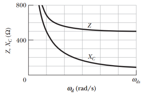
An alternating source with a variable frequency, a capacitor with capacitance C, and a resistor with resistance R are connected in series. Figure 31-29 gives the impedance Z of the circuit versus the driving angular frequency ωd; the curve reaches an asymptote of 500 Ω, and the horizontal scale is set by ωds = 300 rad/s. The figure also gives the reactance Xc for the capacitor versus ωd. What are (a) R and (b) C?
In an L-R-C series circuit, suppose R = 300 ohms, L = 60 mH, C = 0.50 uF, V = 50 V, and w = 10,000 rad/s. Find 4) the phase angle φ, and 5) the voltage amplitude across each circuit element (inductor, resistor, capacitor).
In a series circuit LRC has R = 20ohm, L = 0.16H, C = 30 mF and an AC voltage source peak 250V. For a certain angular frequency, the power factor of the circuit becomes unity and the circuit consumes maximum power. Find:
a) the angular frequency.
b) the inductive reactance, the capacitive reactance, the circuit impedance.
c) the phase angle Fi/Phi(?) and the maximum current in the circuit.
d) the peak voltage across the resistor, the peak voltage across the inductor, and the peak voltage across the capacitor.
Suppose a 0.55 mH inductor is connected to a 37.5 μF capacitor.
Find the resonant frequency, in hertz.
The simple AC circuit shown on the right has resistance R = 47.5 Ω and impedance Z = 165 Ω. The rms voltage of the power supply is ΔVrms = 196 V.
(a) Express the rms current, Irms, in terms of ΔVrms and Z.
(b) Calculate the numerical value of Irms in amps. (c) Express the average power dissipated in the circuit, Pavg, in terms of Irms and R. (d) Calculate the value of Pavg, in watts.
Need a deep-dive on the concept behind this application? Look no further. Learn more about this topic, physics and related others by exploring similar questions and additional content below.


 Physics for Scientists and Engineers: Foundations...PhysicsISBN:9781133939146Author:Katz, Debora M.Publisher:Cengage Learning