
Videos
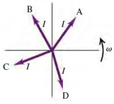
The accompanying figure shows four different current phasors with the same angular frequency ω. At the time shown, which phasor corresponds to (a) a positive current that is becoming more positive; (b) a positive current that is decreasing toward zero; (c) a negative current that is becoming more negative; (d) a negative current that is decreasing in magnitude toward zero?

Learn your wayIncludes step-by-step video

Chapter 31 Solutions
University Physics with Modern Physics, Books a la Carte Edition; Modified MasteringPhysics with Pearson eText -- ValuePack Access Card -- for ... eText -- Valuepack Access Card (14th Edition)
Additional Science Textbook Solutions
Introduction to Electrodynamics
Life in the Universe (4th Edition)
Conceptual Physical Science (6th Edition)
Physics (5th Edition)
Physics: Principles with Applications
Sears And Zemansky's University Physics With Modern Physics


- Q3: 42. Find and graph the charge q(t) and the current i(t) in the LC-circuit in Fig. 151, assuming L 1 H, C = 1 F, v(t) = 1 - e-t if 0 T, and zero initial current and charge. v(t) Fig. 151. LC-circuitarrow_forwardb) Two parallel straight wire, X and Y are separated at a distance 15 m between each other as UTM shown in Figure 2. The currents in wire X and Y is 20 A and 10 direction of the current is opposite and the length of each wire is 5 m. Calculate: A respectively when the UTM UTM X UTM &U Y 5UTM UTM M UTM UTM UTM U UTM. UTM i. M UTM UTM Figure 2 the magnitude and direction of the total magnetic field at the point midway between the wires. ii. the magnitude of the net force per unit length experienced by the wires. eUTM 3 UTM S UTM UTM 5 UTMarrow_forwardThe figure below shows the charge on a capacitor and the current through the resistor as a function of time in a RC circuit. Fig A: Charge VS. Time Capacitor. Fig B: Current Vs. Time Resistor. Charge vs. Time Capacitor Current vs. Time Resistor 0.368 lo 0.368 Qoʻ 17 27 37 47 57 17 27 37 47 57 Time (s) Time (s) (a) (b) Part A: Do these graphs represent the charging or the discharging of the capacitor? Explain. Part B: Calculations (i) If t= 0.09, construct an RC circuit choosing values of R and C that would represent the graphs the above. Explain how you arrived at the choice? If t = 0.1, construct an RC circuit choosing values of R and C that would represent the graphs the above. Explain how you arrived at the choice? (ii) Charge (C) Current (A)arrow_forward
- Problem 9: A current passing through a resistor (R = 25 2) decreases exponentially with time as I(t) = Ioe at where Io = 5.5 A and a = 0.15 s-1. %3D Part (a) Calculate the energy dissipated by the resistor in joules during the first 10 seconds. E = || sin() cos() tan() 7 8 9 НOME E 1^ AL 4 5 6 1 2 3 cotan() asin() acos() atan() acotan() sinh() cosh() tanh() cotanh() + END O Degrees Radians VO BАСKSPАСЕ DEL CLEAR Submit Hint Feedback I give up! Part (b) Calculate the total energy dissipated by the resistor in joules as time goes to infinity.arrow_forwardWhy there is a phase shift between the measured voltage VL and current I ?arrow_forward12 V Figure 2: 3.In figure 2. Assume the direction of the currents are correct but the polarity of the battery through which the current of 1A is flowing may or may not be correct. (a) The current I-1+2 = 3A. (True, False) (b) For the loop on the left: -(3)(2) -e+ (1)(1) - 0 which leads to e- -5 indicating that the assigned polarity of the battery is incorrect. (True, False) (c) the resistance r can be found from: -(3)(2) + 12 - 3r =0 leading to r= 2. (True, False) (d) If (a) and (c) are true then the power dissipated by the resistor r and power supplied by the 12V battery are is 18 Watts and 36 Watts respectively. (True, False) (e) If (b) is true then the power dissipated by the 1n resistor, the 20 resistor and the power supplied to the 5V battery are 1 Watt, 12 Watt and 5 Watta respectively. (True, False) (F) If (d) and (e) are true the power delivered by the 12V battery is +36Watts. The power dissipated by the resistors are 41Watts and power stored in the 5V battery is +5Watts. This…arrow_forward
- A portion of a metal wire is shown below. When connected to a battery, an electric field is set-up which causes electrons to slowly drift with velocities (va) usually on the order of 10 5~ 10-4 m/s. In the set-up below the drift velocity of the electrons is to the right, then the directions of the electric field E and the conventional current are to the respectively AZE right and right right and left O left and left O left and right O both unknownarrow_forwardQuestion 8. A common transistor radio set requires 12 V (D.C.) for its operation. The D.C. source is constructed by using a transformer and a rectifier circuit, which are operated at 220 V (A.C.) on standard domestic A.C. supply. The number of turns of the secondary coil are 24, then the number of turns of the primary are ______.arrow_forwardThe switch shown has been in position a for a long time. It is changed to position b at t = 0 s. What are the charge Q on the capacitor and the current I through the resistor (a) immediately after the switch is changed? (b) At t = 50 ms? (c) At t = 200 μs?arrow_forward
- R1 S R3. R2 4. Determine in the current in each resistor given that R1 = R2 = R3 = 12, the capacitance C = 0.5 µF, and potential across the batter of E = 2V when the switch is closed at t = 0. Determine then after some time (t = x) after the switch is closed the currents in each resistor.arrow_forward(a). A silver wire 6.6 mm with diameter in which 3.6 ampere current passing through. Calculate how manycoulombs of electric charge flows from silver wire in 3.0 hour. (b). The thin copper wire with radius of 1.3 mm is wound into a torus shaped coil as revealed in figure.From copper wire 8.75 x 10⁻²ampere electric current passing though in 4800 sec. Number of free electronsper cubic meter in copper wire is 5.8 x 1028. Calculate magnitude of electron’s drift velocity in thediameter of copper wire.arrow_forward(5) Current is flowing through a cylindrical copper wire with radius 6.33mm and length 92.1cm. This wire is hooked up to two capacitors in series C1 The capacitors both have cross sectional areas of A = 179cm2. (a) At a given moment in time, the current is I electrons is vd = 9.42µF and C2 = 8.11µF. = 77.97A and the drift velocity of the 45.6µm/s. What is the number density of electrons in this wire? (b) At a given moment in time, the charge on capacitor 2 is 62.6µC. What is the total change in potential across both capacitors combined? | (c) At the moment described in part (b), what is the energy stored in capacitor 2? (d) At the moment described in part (b), what is the energy density of the electric field in capacitor 2? :arrow_forward
 Physics for Scientists and Engineers, Technology ...PhysicsISBN:9781305116399Author:Raymond A. Serway, John W. JewettPublisher:Cengage Learning