PHYSICS 1250 PACKAGE >CI<
9th Edition
ISBN: 9781305000988
Author: SERWAY
Publisher: CENGAGE LEARNING (CUSTOM)
expand_more
expand_more
format_list_bulleted
Videos
Textbook Question
Chapter 32, Problem 32.24P
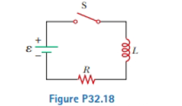
Consider the circuit in Figure P32.18, taking ε = 6.00 V, L = 8.00 mH, and R = 4.00 Ω. (a) What is the inductive time constant of the circuit? (b) Calculate the current in the circuit 250 μs after the switch is closed. (c) What is the value of the final steady-state current? (d) After what time interval does the current reach 80.0% of its maximum value?
Expert Solution & Answer

Trending nowThis is a popular solution!

Students have asked these similar questions
For physics lab, two students constructed an RL circuit similar to the one shown in the figure, with & = 6.00 V,
L 7.80 mH, and R = 7.60 0.
R
www
Ⓡ
(a) What is the inductive time constant of the circuit (in ms)?
ms
ele
(b) Calculate the current in the circuit (in A) 250 us after the switch is closed.
A
A
(c) What is the value of the final steady-state current (in A)?
A
ms
(d) After what time interval (in ms) does the current reach 80.0% of its maximum value?
40
In the circuit of as shown, the battery emf is 50.0 V, the resistance is 250 Ω, and the capacitance is 0.500 μF. The switch S is closed for a long time interval, and zero potential difference is measured across the capacitor. After the switch is opened, the potential difference across the capacitor reaches a maximum value of 150 V. What is the value of the inductance?
A battery of emf E is connected in series with a resistor, an inductor L, and a switch S. A capacitor C is connected in parallel to the inductor. When the switch is left in the closed position for a long time, the potential difference across the
capacitor is zero. The switch is opened and the maximum potential difference across the capacitor is measured to be 140 V. Determine the capacitance of the capacitor if E = 60 V, R = 125 N, and L = 54.0 mH.
ww
R
Chapter 32 Solutions
PHYSICS 1250 PACKAGE >CI<
Ch. 32 - A coil with zero resistance has its ends labeled a...Ch. 32 - Prob. 32.2QQCh. 32 - Prob. 32.3QQCh. 32 - Prob. 32.4QQCh. 32 - (i) At an instant of time during the oscillations...Ch. 32 - Prob. 32.1OQCh. 32 - Prob. 32.2OQCh. 32 - Prob. 32.3OQCh. 32 - In Figure OQ32.4, the switch is left in position a...Ch. 32 - Prob. 32.5OQ
Ch. 32 - Prob. 32.6OQCh. 32 - Prob. 32.7OQCh. 32 - Prob. 32.1CQCh. 32 - Prob. 32.2CQCh. 32 - A switch controls the current in a circuit that...Ch. 32 - Prob. 32.4CQCh. 32 - Prob. 32.5CQCh. 32 - Prob. 32.6CQCh. 32 - The open switch in Figure CQ32.7 is thrown closed...Ch. 32 - After the switch is dosed in the LC circuit shown...Ch. 32 - Prob. 32.9CQCh. 32 - Discuss the similarities between the energy stored...Ch. 32 - Prob. 32.1PCh. 32 - Prob. 32.2PCh. 32 - Prob. 32.3PCh. 32 - Prob. 32.4PCh. 32 - An emf of 24.0 mV Ls induced in a 500-turn coil...Ch. 32 - Prob. 32.6PCh. 32 - Prob. 32.7PCh. 32 - Prob. 32.8PCh. 32 - Prob. 32.9PCh. 32 - Prob. 32.10PCh. 32 - Prob. 32.11PCh. 32 - A toroid has a major radius R and a minor radius r...Ch. 32 - Prob. 32.13PCh. 32 - Prob. 32.14PCh. 32 - Prob. 32.15PCh. 32 - Prob. 32.16PCh. 32 - Prob. 32.17PCh. 32 - Prob. 32.18PCh. 32 - Prob. 32.19PCh. 32 - When the switch in Figure P32.18 is closed, the...Ch. 32 - Prob. 32.21PCh. 32 - Show that i = Iiet/ is a solution of the...Ch. 32 - Prob. 32.23PCh. 32 - Consider the circuit in Figure P32.18, taking =...Ch. 32 - Prob. 32.25PCh. 32 - The switch in Figure P31.15 is open for t 0 and...Ch. 32 - Prob. 32.27PCh. 32 - Prob. 32.28PCh. 32 - Prob. 32.29PCh. 32 - Two ideal inductors, L1 and L2, have zero internal...Ch. 32 - Prob. 32.31PCh. 32 - Prob. 32.32PCh. 32 - Prob. 32.33PCh. 32 - Prob. 32.34PCh. 32 - Prob. 32.35PCh. 32 - Complete the calculation in Example 31.3 by...Ch. 32 - Prob. 32.37PCh. 32 - A flat coil of wire has an inductance of 40.0 mH...Ch. 32 - Prob. 32.39PCh. 32 - Prob. 32.40PCh. 32 - Prob. 32.41PCh. 32 - Prob. 32.42PCh. 32 - Prob. 32.43PCh. 32 - Prob. 32.44PCh. 32 - Prob. 32.45PCh. 32 - Prob. 32.46PCh. 32 - In the circuit of Figure P31.29, the battery emf...Ch. 32 - A 1.05-H inductor is connected in series with a...Ch. 32 - A 1.00-F capacitor is charged by a 40.0-V power...Ch. 32 - Calculate the inductance of an LC circuit that...Ch. 32 - An LC circuit consists of a 20.0-mH inductor and a...Ch. 32 - Prob. 32.52PCh. 32 - Prob. 32.53PCh. 32 - Prob. 32.54PCh. 32 - An LC circuit like the one in Figure CQ32.8...Ch. 32 - Show that Equation 32.28 in the text Ls Kirchhoffs...Ch. 32 - In Figure 31.15, let R = 7.60 , L = 2.20 mH, and C...Ch. 32 - Consider an LC circuit in which L = 500 mH and C=...Ch. 32 - Electrical oscillations are initiated in a series...Ch. 32 - Review. Consider a capacitor with vacuum between...Ch. 32 - Prob. 32.61APCh. 32 - An inductor having inductance I. and a capacitor...Ch. 32 - A capacitor in a series LC circuit has an initial...Ch. 32 - Prob. 32.64APCh. 32 - When the current in the portion of the circuit...Ch. 32 - At the moment t = 0, a 24.0-V battery is connected...Ch. 32 - Prob. 32.67APCh. 32 - Prob. 32.68APCh. 32 - Prob. 32.69APCh. 32 - At t = 0, the open switch in Figure P31.46 is...Ch. 32 - Prob. 32.71APCh. 32 - Prob. 32.72APCh. 32 - Review. A novel method of storing energy has been...Ch. 32 - Prob. 32.74APCh. 32 - Review. The use of superconductors has been...Ch. 32 - Review. A fundamental property of a type 1...Ch. 32 - Prob. 32.77APCh. 32 - In earlier times when many households received...Ch. 32 - Assume the magnitude of the magnetic field outside...Ch. 32 - Prob. 32.80CPCh. 32 - To prevent damage from arcing in an electric...Ch. 32 - One application of an RL circuit is the generation...Ch. 32 - Prob. 32.83CP
Knowledge Booster


Learn more about
Need a deep-dive on the concept behind this application? Look no further. Learn more about this topic, physics and related others by exploring similar questions and additional content below.Similar questions
- In an oscillating RLC circuit, R = 7.0 L. = 10 mH. And C = 3.0 F. Initially, the capacitor has a charge of 8.0 C and the current is zero. Calculate the charge on the capacitor (a) five cycles later and (b) 50 cycles later.arrow_forwardIn the LC circuit in Figure 33.11, the inductance is L = 19.8 mH and the capacitance is C = 19.6 mF. At some moment, UB = UE= 17.5 mJ. a. What is the maximum charge stored by the capacitor? b. What is the maximum current in the circuit? c. At t = 0, the capacitor is fully charged. Write an expression for the charge stored by the capacitor as a function of lime. d. Write an expression for the current as a function of time.arrow_forwardA step-up transformer connected to a 100-V line U used to supply a hydrogen-gas discharge tube with 5.0 kV (rms). The tube dissipates 75 W of power, (a) What is the ratio of the number of turns in the secondary winding to the number of turns in the primary winding? (b) What are the nns currents in the primary and secondary windings? (c) What is the effective resistance seen by the 110-V source?arrow_forward
- Consider the RL circuit in the figure with R=10.00 Ω, L1=1.80 H, L2=3.90 H, and V=5.0 V. At time t=0, the switch is closed to connect the circuit to a constant emf. How long (in seconds) does it take for the current to reach a value of Imax/2.71828 of its maximum value, where Imax is the maximum current through the circuit?arrow_forwardA 10.00 μF capacitor C is initially charged to a voltage V of 10.00 (V). It is then connected in series with an inductor L. Charge and current oscillations ensue. (a) What is the total energy U of the circuit? (b) If the maximum current in the inductor is Im = 0.500 (A), then what is the inductance L? What is the charge Q on the positive plate of the capacitor when the current reaches its maximum value Im? (c) What is the angular frequency of the charge oscillations?arrow_forwardA resistor and an inductor are connected in series to a battery with emf 240 V and negligible internal resistance. The circuit is completed at time t=0. At a later time t=T the current is 7.00 A and is increasing at a rate of 20.0 A/s. After a long time the current in the circuit is 15.0 A. What is the value of T , the time when the current is 7.00 A ?arrow_forward
- The capacitor in the circuit shown below is initially uncharged. The switch is closed at t = 0 s. ΔVbattery = 60 V, C = 2.0 F, and R = 3.0 Ω. What is the current in the circuit immediately after the switch is closed, in Ampere?arrow_forwardThe output EMF of a generator is given by V (t) = a sin(wt), where a = 231 V. Find the rms current in the circuit when this generator is connected to a 118 N resistor. Answer in units of A.arrow_forwardAn RLC circuit consists of a 46.3 2 resistor, a 2.47 µF capacitor, and a 4.16 mH inductor. Initially, the voltage across the capacitor is 3.08 V, and no current is flowing in the circuit. How many oscillations occur as the charge amplitude on the capacitor decays to 10.3 × 10⁶ of its initial value? It is not acceptable to let w' = @. i oscillations (include decimals if needed to keep the appropriate number of significant digits)arrow_forward
- An RL circuit has an emf source of 28 v, a 62 resistor, a 38 H inductor, and a switch. At what rate, as a function of t, does the emf across the inductor change after the switch is closed?arrow_forwardIn and L-C circuit, C=3.19 microFarads and L=81.0 mH. During the oscillations the maximum current in the inductor is 0.855 mA. What is the magnitude of the charge on the capacitor at an instant when the current in the inductor has magnitude 0.501 mA? Express your answer in Coloumbs.arrow_forwardFor physics lab, two students constructed an RL circuit similar to the one shown in the figure, with = 6.00 V, L = 5.40 mH, and R = 8.00 Q. S R ele L (a) What is the inductive time constant of the circuit (in ms)? 0.065 X Apply the definition of the inductive time constant. ms ms (b) Calculate the current in the circuit (in A) 250 µs after the switch is closed. A (c) What is the value of the final steady-state current (in A)? A (d) After what time interval (in ms) does the current reach 80.0% of its maximum value?arrow_forward
arrow_back_ios
SEE MORE QUESTIONS
arrow_forward_ios
Recommended textbooks for you
 Physics for Scientists and Engineers, Technology ...PhysicsISBN:9781305116399Author:Raymond A. Serway, John W. JewettPublisher:Cengage Learning
 Principles of Physics: A Calculus-Based TextPhysicsISBN:9781133104261Author:Raymond A. Serway, John W. JewettPublisher:Cengage Learning
 Physics for Scientists and Engineers: Foundations...PhysicsISBN:9781133939146Author:Katz, Debora M.Publisher:Cengage Learning
 Physics for Scientists and EngineersPhysicsISBN:9781337553278Author:Raymond A. Serway, John W. JewettPublisher:Cengage Learning
 Physics for Scientists and Engineers with Modern ...PhysicsISBN:9781337553292Author:Raymond A. Serway, John W. JewettPublisher:Cengage Learning
Physics for Scientists and Engineers, Technology ...
Physics
ISBN:9781305116399
Author:Raymond A. Serway, John W. Jewett
Publisher:Cengage Learning
Principles of Physics: A Calculus-Based Text
Physics
ISBN:9781133104261
Author:Raymond A. Serway, John W. Jewett
Publisher:Cengage Learning
Physics for Scientists and Engineers: Foundations...
Physics
ISBN:9781133939146
Author:Katz, Debora M.
Publisher:Cengage Learning
Physics for Scientists and Engineers
Physics
ISBN:9781337553278
Author:Raymond A. Serway, John W. Jewett
Publisher:Cengage Learning
Physics for Scientists and Engineers with Modern ...
Physics
ISBN:9781337553292
Author:Raymond A. Serway, John W. Jewett
Publisher:Cengage Learning
Introduction To Alternating Current; Author: Tutorials Point (India) Ltd;https://www.youtube.com/watch?v=0m142qAZZpE;License: Standard YouTube License, CC-BY