
EBK PHYSICS FOR SCIENTISTS AND ENGINEER
9th Edition
ISBN: 8220100546310
Author: Jewett
Publisher: CENGAGE L
expand_more
expand_more
format_list_bulleted
Videos
Textbook Question
thumb_up100%
Chapter 32, Problem 32.4OQ
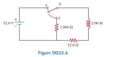
In Figure OQ32.4, the switch is left in position a for a long lime interval and is then quickly thrown to position b. Rank the magnitudes of the voltages across the Four circuit elements a short time thereafter from the largest to the smallest.
Expert Solution & Answer

Trending nowThis is a popular solution!

Students have asked these similar questions
Switch S in in the figure is closed at time t = 0, to begin charging an initially uncharged capacitor of capacitance C = 17.2 μF through a resistor of resistance R = 21.2 Ω. At what time is the potential across the capacitor equal to that across the resistor?
You connect a battery, resistor, and capacitor as in (Figure 1), where R = 14.0 Ω and C = 3.00 ×10^-6 F. The switch S is closed at t = 0. When the current in the circuit has magnitude 3.00 A, the charge on the capacitor is 40.0 × 10^−6 C.
At what time t after the switch is closed is the charge on the capacitor equal to 40.0 x 10^-6 C?
When the current has magnitude 3.00 A, at what rate is energy being stored in the capacitor?
In the figure, suppose the switch has been closed for a length of time sufficiently long for the capacitor to become fully charged. For this circuit, R1 = 12.0 kΩ, R2 = 15.0 kΩ, R3 = 3.000 kΩ, C = 10.0 μF , and emf = 9.00 V. Find (d) the potential differance across R2. (e) the charge on the capacitor.
Chapter 32 Solutions
EBK PHYSICS FOR SCIENTISTS AND ENGINEER
Ch. 32 - A coil with zero resistance has its ends labeled a...Ch. 32 - Prob. 32.2QQCh. 32 - Prob. 32.3QQCh. 32 - Prob. 32.4QQCh. 32 - (i) At an instant of time during the oscillations...Ch. 32 - Prob. 32.1OQCh. 32 - Prob. 32.2OQCh. 32 - Prob. 32.3OQCh. 32 - In Figure OQ32.4, the switch is left in position a...Ch. 32 - Prob. 32.5OQ
Ch. 32 - Prob. 32.6OQCh. 32 - Prob. 32.7OQCh. 32 - Prob. 32.1CQCh. 32 - Prob. 32.2CQCh. 32 - A switch controls the current in a circuit that...Ch. 32 - Prob. 32.4CQCh. 32 - Prob. 32.5CQCh. 32 - Prob. 32.6CQCh. 32 - The open switch in Figure CQ32.7 is thrown closed...Ch. 32 - After the switch is dosed in the LC circuit shown...Ch. 32 - Prob. 32.9CQCh. 32 - Discuss the similarities between the energy stored...Ch. 32 - Prob. 32.1PCh. 32 - Prob. 32.2PCh. 32 - Prob. 32.3PCh. 32 - Prob. 32.4PCh. 32 - An emf of 24.0 mV Ls induced in a 500-turn coil...Ch. 32 - Prob. 32.6PCh. 32 - Prob. 32.7PCh. 32 - Prob. 32.8PCh. 32 - Prob. 32.9PCh. 32 - Prob. 32.10PCh. 32 - Prob. 32.11PCh. 32 - A toroid has a major radius R and a minor radius r...Ch. 32 - Prob. 32.13PCh. 32 - Prob. 32.14PCh. 32 - Prob. 32.15PCh. 32 - Prob. 32.16PCh. 32 - Prob. 32.17PCh. 32 - Prob. 32.18PCh. 32 - Prob. 32.19PCh. 32 - When the switch in Figure P32.18 is closed, the...Ch. 32 - Prob. 32.21PCh. 32 - Show that i = Iiet/ is a solution of the...Ch. 32 - Prob. 32.23PCh. 32 - Consider the circuit in Figure P32.18, taking =...Ch. 32 - Prob. 32.25PCh. 32 - The switch in Figure P31.15 is open for t 0 and...Ch. 32 - Prob. 32.27PCh. 32 - Prob. 32.28PCh. 32 - Prob. 32.29PCh. 32 - Two ideal inductors, L1 and L2, have zero internal...Ch. 32 - Prob. 32.31PCh. 32 - Prob. 32.32PCh. 32 - Prob. 32.33PCh. 32 - Prob. 32.34PCh. 32 - Prob. 32.35PCh. 32 - Complete the calculation in Example 31.3 by...Ch. 32 - Prob. 32.37PCh. 32 - A flat coil of wire has an inductance of 40.0 mH...Ch. 32 - Prob. 32.39PCh. 32 - Prob. 32.40PCh. 32 - Prob. 32.41PCh. 32 - Prob. 32.42PCh. 32 - Prob. 32.43PCh. 32 - Prob. 32.44PCh. 32 - Prob. 32.45PCh. 32 - Prob. 32.46PCh. 32 - In the circuit of Figure P31.29, the battery emf...Ch. 32 - A 1.05-H inductor is connected in series with a...Ch. 32 - A 1.00-F capacitor is charged by a 40.0-V power...Ch. 32 - Calculate the inductance of an LC circuit that...Ch. 32 - An LC circuit consists of a 20.0-mH inductor and a...Ch. 32 - Prob. 32.52PCh. 32 - Prob. 32.53PCh. 32 - Prob. 32.54PCh. 32 - An LC circuit like the one in Figure CQ32.8...Ch. 32 - Show that Equation 32.28 in the text Ls Kirchhoffs...Ch. 32 - In Figure 31.15, let R = 7.60 , L = 2.20 mH, and C...Ch. 32 - Consider an LC circuit in which L = 500 mH and C=...Ch. 32 - Electrical oscillations are initiated in a series...Ch. 32 - Review. Consider a capacitor with vacuum between...Ch. 32 - Prob. 32.61APCh. 32 - An inductor having inductance I. and a capacitor...Ch. 32 - A capacitor in a series LC circuit has an initial...Ch. 32 - Prob. 32.64APCh. 32 - When the current in the portion of the circuit...Ch. 32 - At the moment t = 0, a 24.0-V battery is connected...Ch. 32 - Prob. 32.67APCh. 32 - Prob. 32.68APCh. 32 - Prob. 32.69APCh. 32 - At t = 0, the open switch in Figure P31.46 is...Ch. 32 - Prob. 32.71APCh. 32 - Prob. 32.72APCh. 32 - Review. A novel method of storing energy has been...Ch. 32 - Prob. 32.74APCh. 32 - Review. The use of superconductors has been...Ch. 32 - Review. A fundamental property of a type 1...Ch. 32 - Prob. 32.77APCh. 32 - In earlier times when many households received...Ch. 32 - Assume the magnitude of the magnetic field outside...Ch. 32 - Prob. 32.80CPCh. 32 - To prevent damage from arcing in an electric...Ch. 32 - One application of an RL circuit is the generation...Ch. 32 - Prob. 32.83CP
Knowledge Booster


Learn more about
Need a deep-dive on the concept behind this application? Look no further. Learn more about this topic, physics and related others by exploring similar questions and additional content below.Similar questions
- In Figure 33.9A (page 1052), the switch is closed at a at t = 0. Find an expression for the power dissipated by the resistor as a function of time, and sketch your result. Is the power lost greater as soon as the switch is closed or a long time after it has been closed? Does your answer make sense?arrow_forwardIn the circuit of Figure P27.25, the switch S has been open for a long time. It is then suddenly closed. Determine the time constant (a) before the switch is closed and (b) after the switch is closed. (c) Let the switch be closed at t = 0. Determine the current in the switch as a function of time. Figure P27.25 Problems 25 and 26.arrow_forwardC S R In the circuit shown above, let C = 12.31 μF and R = 4.88 M. If the switch is initially open and the voltage on the capacitor is 47.9 V, what will be the voltage on the capacitor after 13.55 s?arrow_forward
- To get the maximum current, the connection should be in parallel. If you create a parallel connection with 30V DC source and three resistors with R1 = 50Ω, R2 = 75Ω, and R3 = 100Ω, how do you calculate for the total current (IT) and the current flowing in each resistor (I1, I2, I3), and the total voltage (VT) and the voltage across each resistor (V1, V2, V3)? How do you also determine the power dissipated by each resistor (P1, P2, P3) and by the whole circuit (PT)??arrow_forwardProblem #2: Maxwell's Equations. Consider the RC circuit shown. It consists of: an ideal 18 V battery, E a 30 resistor, and a 15 mF capacitor. R The capacitor consists of two circular plates separated by a small distance. Each plate has radius R € 0.46 m. The capacitor is initially uncharged. GH = At time t = 0, the switch is closed. с 3. How fast is the electric flux between the capacitor plates changing at the instant the switch is closed? S 4. When the current through the resistor is 0.40 A, what is the magnetic field at point H, a distance of 0.35 m from the center of the capacitor?arrow_forwardUseful Constants: k = 9.00 × 10º Nm² C2 8.85 x 10⁻¹² C² Nm2 %3D e = 1.6 x 10⁻¹⁹ C me = 9.11 x 10 mp = 1.67 × 10⁻²⁷kg %3D -27 mn = 1.68 x 10 %3Darrow_forward
- You connect a battery, resistor, and capacitor as in (Figure 1), where E = 46.0 V, C = 5.00 μF, and R = 130 Ω. The switch S is closed at t = 0. When the voltage across the capacitor is 8.00 VV, what is the magnitude of the current in the circuit? At what time tt after the switch is closed is the voltage across the capacitor 8.00 V? When the voltage across the capacitor is 8.00 V, at what rate is energy being stored in the capacitor?arrow_forwardA circuit is comprised of two adjacent square loops that share a side such that the right side of the left loop is also the left side of the right loop. The two loops meet at point a at the top of the shared side and point b at the bottom of the shared side. The left side of the left loop contains a resistor R and a current I3 that points upwards. The top side of the left loop contains a battery with voltage emf ℰ oriented such that the positive terminal is on the right and the negative is on the left. The right side of the right loop contains a 6.0 Ω resistor and a current I1 that points downwards. The top side of the right loop contains a 24 V battery oriented such that the positive terminal is on the right and the negative is on the left. The shared side contains a 3.0 Ω resistor and a current I2 that points downwards. In the circuit of the figure below, the current I1 is 3.5 A and the values of and R are unknown. What are the currents I2 and I3? (Enter the magnitude only.) I2=?A…arrow_forwardConsider the circuit shown in the figure below, where L = 5.45 mH and R2 = 500 Ω. The switch S can be positioned at either a or b. A circuit contains a battery, a switch, an inductor, and two resistors. The battery is labeled 24.0 V and is on the left side of the circuit. The positive terminal is above the negative terminal. The circuit starts at the positive terminal and extends directly up, then directly to the right where it reaches the switch at a point labeled a. The switch is labeled S and allows the circuit to alternate between two paths. The first path starts at the positive terminal of the battery, goes up and then to the right through the switch from the point labeled a to a point without a label, goes to the right through the inductor labeled L at the top of the circuit, goes down through the resistors labeled R1 and R2 placed in parallel with each other on the right side of the circuit, goes to the left through a wire running directly from the right side of the circuit…arrow_forward
- An uncharged capacitor is connected in series with a resistor, a dc battery and an open switch. At time t = 0 s, the switch is closed. Which of the graphs below best describes the magnitude of the potential difference V across the resistor as a function of time t?arrow_forwardAt time t=0, the switch in the circuit shown in the figure is closed. After a sufficiently long time, steady currents I1 ,I2 and I3 flow through resistors R1 ,R2 and R3 , respectively. Determine these three currents.arrow_forwardIn the circuit below, the capacitor starts out uncharged. The resistance is R = 118 Ω, capacitance is C = 0.0647 F, and the battery emf is 16.7 V. What is the charge (Q) on the capacitor at a time of t = 3.72 seconds after the switch is closed?arrow_forward
arrow_back_ios
SEE MORE QUESTIONS
arrow_forward_ios
Recommended textbooks for you
 Physics for Scientists and Engineers: Foundations...PhysicsISBN:9781133939146Author:Katz, Debora M.Publisher:Cengage Learning
 Physics for Scientists and EngineersPhysicsISBN:9781337553278Author:Raymond A. Serway, John W. JewettPublisher:Cengage Learning
 Physics for Scientists and Engineers with Modern ...PhysicsISBN:9781337553292Author:Raymond A. Serway, John W. JewettPublisher:Cengage Learning
 Principles of Physics: A Calculus-Based TextPhysicsISBN:9781133104261Author:Raymond A. Serway, John W. JewettPublisher:Cengage Learning
Physics for Scientists and Engineers: Foundations...
Physics
ISBN:9781133939146
Author:Katz, Debora M.
Publisher:Cengage Learning
Physics for Scientists and Engineers
Physics
ISBN:9781337553278
Author:Raymond A. Serway, John W. Jewett
Publisher:Cengage Learning
Physics for Scientists and Engineers with Modern ...
Physics
ISBN:9781337553292
Author:Raymond A. Serway, John W. Jewett
Publisher:Cengage Learning
Principles of Physics: A Calculus-Based Text
Physics
ISBN:9781133104261
Author:Raymond A. Serway, John W. Jewett
Publisher:Cengage Learning
Introduction To Alternating Current; Author: Tutorials Point (India) Ltd;https://www.youtube.com/watch?v=0m142qAZZpE;License: Standard YouTube License, CC-BY