
Concept explainers
(a)
The inductor behaves like an open circuit or short circuit or a resister of some particular resistance or none of those choices before the switch is opened.
(a)
Answer to Problem 32.64AP
Explanation of Solution
Given info: The induced voltage is
The inductor has no resistance. If the switch is closed for a long time, then inductor will reach saturation and voltage passes through the inductor. Hence, it behaves as a short circuit.
Conclusion:
Therefore, the inductor behaves as the short circuit because of no resistance.
(b)
The current carried by the inductor.
(b)
Answer to Problem 32.64AP
Explanation of Solution
Given info: The induced voltage is
The figure of the circuit diagrammed referred from P31.15 is shown below.
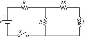
Figure (1)
The net resistance for parallel combination is,
Here,
The net resistance is connected in series with
Here,
Substitute
Substitute
Formula to calculate the current of battery is,
Here,
Substitute
The voltage across the parallel combination of resistors is,
Substitute
Formula to calculate the current though the inductor is,
Substitute
Conclusion:
Therefore, the current carried by the inductor for
(c)
The energy stored in the inductor.
(c)
Answer to Problem 32.64AP
Explanation of Solution
Given info: The induced voltage is
Formula to calculate the energy stored in the inductor is,
Substitute
Thus, the energy stored in the inductor for
Conclusion:
Therefore, the energy stored in the inductor for
(d)
The energy previously stored in the inductor after the switch is opened.
(d)
Answer to Problem 32.64AP
Explanation of Solution
Given info: The induced voltage is
When switch is opened, the energy stored in the inductor will dissipate through resistor
Conclusion:
Therefore, the energy becomes
(e)
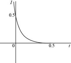
To draw: The graph of the current in the inductor for
(e)
Answer to Problem 32.64AP
Answer The graph of the current in the inductor for
Explanation of Solution
Introduction:
The graph of the current verses time shows the variation of the current in the circuit with time and tells the nature of the current.
Explanation:
Given info: The induced voltage is
After time
Formula to calculate the time constant is,
Substitute
Substitute
The current flowing through the inductor at time
Substitute
Thus, the graph of the current (the initial and final values) in the inductor for
Figure (2)
The graph shows that current decays with exponentially with time constant. The current decreases from
Want to see more full solutions like this?
Chapter 32 Solutions
EBK PHYSICS FOR SCIENTISTS AND ENGINEER


- Figure P23.58 is a graph of the induced emf versus time for a coil of N turns rotating with angular speed ω in a uniform magnetic field directed perpendicular to the coil’s axis of rotation. What If? Copy this sketch (on a larger scale) and on the same set of axes show the graph of emf versus t (a) if the number of turns in the coil is doubled, (b) if instead the angular speed is doubled, and (c) if the angular speed is doubled while the number of turns in the coil is halved. Figure P23.58arrow_forwardA loop of wire in the shape of a rectangle of width w and length L and a long, straight wire carrying a current I lie on a tabletop as shown in Figure P23.7. (a) Determine the magnetic flux through the loop due to the current I. (b) Suppose the current is changing with time according to I = a + bt, where a and b are constants. Determine the emf that is induced in the loop if b = 10.0 A/s, h = 1.00 cm, w = 10.0 cm, and L = 1.00 m. (c) What is the direction of the induced current in the rectangle? Figure P23.7arrow_forwardA conducting rod is pulled horizontally with constant force F = 5.00 N along a set of rails separated by d = 0.56 m. A uniform magnetic field B= 0.60 T is directed into the page. There is no friction between the rod and the rails, and the rod moves with constant velocity v = 4.00 m/s. Using Faraday's Law, calculate the magnitude of the induced emf (in V) around the loop in the figure that is caused by the changing flux.arrow_forward
- A toroid having a rectangular cross section (a = 2.00 cm by b = 3.00 cm) and inner radius R = 4.00 cm consists of N = 500 turns of wire that carry a sinusoidal current I = Imax sin t, with Imax = 50.0 A and a frequency f = /2 = 60.0 Hz. A coil that consists of N = 20 turns of wire is wrapped around one section of the toroid as shown in Figure P30.9. Determine the emf induced in the coil as a function of time. Figure P30.9arrow_forwardFigure P30.39 shows a stationary conductor whose shape is similar to the letter e. The radius of its circular portion is a = 50.0 cm. It is placed in a constant magnetic field of 0.500 T directed out of the page. A straight conducting rod, 50.0 cm long, is pivoted about point O and rotates with a constant angular speed of 2.00 rad/s. (a) Determine the induced emf in the loop POQ. Note that the area of the loop is a2/2. (b) If all the conducting material has a resistance per length of 5.00 /m, what is the induced current in the loop POQ at the instant 0.250 s after point P passes point Q? Figure P30.39arrow_forwardAn instrument based on induced emf has been used to measure projectile speeds up to 6 km/s. A small magnet is imbedded in the projectile as shown in Figure P23.2. The projectile passes through two coils separated by a distance d. As the projectile passes through each coil, a pulse of emf is induced in the coil. The time interval between pulses can be measured accurately with an oscilloscope, and thus the speed can be determined. (a) Sketch a graph of V versus t for the arrangement shown. Consider a current that flows counterclockwise as viewed from the starting point of the projectile as positive. On your graph, indicate which pulse is from coil 1 and which is from coil 2. (b) If the pulse separation is 2.40 ms and d = 1.50 m, what is the projectile speed? Figure P23.2arrow_forward
 Physics for Scientists and Engineers with Modern ...PhysicsISBN:9781337553292Author:Raymond A. Serway, John W. JewettPublisher:Cengage Learning
 Physics for Scientists and EngineersPhysicsISBN:9781337553278Author:Raymond A. Serway, John W. JewettPublisher:Cengage Learning
 Physics for Scientists and Engineers, Technology ...PhysicsISBN:9781305116399Author:Raymond A. Serway, John W. JewettPublisher:Cengage Learning
 Physics for Scientists and Engineers: Foundations...PhysicsISBN:9781133939146Author:Katz, Debora M.Publisher:Cengage Learning
 Principles of Physics: A Calculus-Based TextPhysicsISBN:9781133104261Author:Raymond A. Serway, John W. JewettPublisher:Cengage Learning