
EBK PHYSICS FOR SCIENTISTS AND ENGINEER
9th Edition
ISBN: 8220100663987
Author: Jewett
Publisher: Cengage Learning US
expand_more
expand_more
format_list_bulleted
Videos
Textbook Question
Chapter 32, Problem 32.65AP
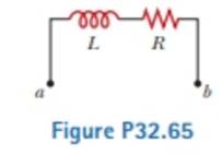
When the current in the portion of the circuit shown in Figure P32.65 is 2.00 A anti increases at a rate of 0.500 A/s, the measured voltage is ΔVab = 9.00 V. When the current is 2.00 A and decreases at the rate of 0.500 A/s. the measured voltage is ΔVab = 5.00 V. Calculate the values of (a) I. and (b) R
Expert Solution & Answer

Trending nowThis is a popular solution!

Students have asked these similar questions
A TV works properly under the voltage of ΔV = 120 V with power P = 1620 W.
(a) Express the current I through the power P and the voltage ΔV.
I=
(b) Calculate the working current of the TV in A.
I=
(c) Express the resistance R through the voltage ΔV and the current I.
R=
(d) Calculate the numerical value of R in Ω.
R=
You have a circuit consisting of a power supply,
switch, resistor, two capacitors, and
voltage/current probes. The resistor has the
value R1 = (1.8 ± 10%) MQ. The capacitors have
%3D
the values C1 = (0.6 ± 20%) µF and C2 = (2.2 ±
20%) µF. The logger pro data resembles the plot
below.
40
35
30
25
20
15
10
1 2 3
5 6
8 9 10 11 12 13 14 15 16 17 18 19 20 21 22 23 24 25
a)
Label the title and all the axes on the
plot above. Identify which region corresponds
to the capacitors charging and discharging. Be
sure to include appropriate units (MKS).
Please answer (b). This is the only incorrect one
Chapter 32 Solutions
EBK PHYSICS FOR SCIENTISTS AND ENGINEER
Ch. 32 - A coil with zero resistance has its ends labeled a...Ch. 32 - Prob. 32.2QQCh. 32 - Prob. 32.3QQCh. 32 - Prob. 32.4QQCh. 32 - (i) At an instant of time during the oscillations...Ch. 32 - Prob. 32.1OQCh. 32 - Prob. 32.2OQCh. 32 - Prob. 32.3OQCh. 32 - In Figure OQ32.4, the switch is left in position a...Ch. 32 - Prob. 32.5OQ
Ch. 32 - Prob. 32.6OQCh. 32 - Prob. 32.7OQCh. 32 - Prob. 32.1CQCh. 32 - Prob. 32.2CQCh. 32 - A switch controls the current in a circuit that...Ch. 32 - Prob. 32.4CQCh. 32 - Prob. 32.5CQCh. 32 - Prob. 32.6CQCh. 32 - The open switch in Figure CQ32.7 is thrown closed...Ch. 32 - After the switch is dosed in the LC circuit shown...Ch. 32 - Prob. 32.9CQCh. 32 - Discuss the similarities between the energy stored...Ch. 32 - Prob. 32.1PCh. 32 - Prob. 32.2PCh. 32 - Prob. 32.3PCh. 32 - Prob. 32.4PCh. 32 - An emf of 24.0 mV Ls induced in a 500-turn coil...Ch. 32 - Prob. 32.6PCh. 32 - Prob. 32.7PCh. 32 - Prob. 32.8PCh. 32 - Prob. 32.9PCh. 32 - Prob. 32.10PCh. 32 - Prob. 32.11PCh. 32 - A toroid has a major radius R and a minor radius r...Ch. 32 - Prob. 32.13PCh. 32 - Prob. 32.14PCh. 32 - Prob. 32.15PCh. 32 - Prob. 32.16PCh. 32 - Prob. 32.17PCh. 32 - Prob. 32.18PCh. 32 - Prob. 32.19PCh. 32 - When the switch in Figure P32.18 is closed, the...Ch. 32 - Prob. 32.21PCh. 32 - Show that i = Iiet/ is a solution of the...Ch. 32 - Prob. 32.23PCh. 32 - Consider the circuit in Figure P32.18, taking =...Ch. 32 - Prob. 32.25PCh. 32 - The switch in Figure P31.15 is open for t 0 and...Ch. 32 - Prob. 32.27PCh. 32 - Prob. 32.28PCh. 32 - Prob. 32.29PCh. 32 - Two ideal inductors, L1 and L2, have zero internal...Ch. 32 - Prob. 32.31PCh. 32 - Prob. 32.32PCh. 32 - Prob. 32.33PCh. 32 - Prob. 32.34PCh. 32 - Prob. 32.35PCh. 32 - Complete the calculation in Example 31.3 by...Ch. 32 - Prob. 32.37PCh. 32 - A flat coil of wire has an inductance of 40.0 mH...Ch. 32 - Prob. 32.39PCh. 32 - Prob. 32.40PCh. 32 - Prob. 32.41PCh. 32 - Prob. 32.42PCh. 32 - Prob. 32.43PCh. 32 - Prob. 32.44PCh. 32 - Prob. 32.45PCh. 32 - Prob. 32.46PCh. 32 - In the circuit of Figure P31.29, the battery emf...Ch. 32 - A 1.05-H inductor is connected in series with a...Ch. 32 - A 1.00-F capacitor is charged by a 40.0-V power...Ch. 32 - Calculate the inductance of an LC circuit that...Ch. 32 - An LC circuit consists of a 20.0-mH inductor and a...Ch. 32 - Prob. 32.52PCh. 32 - Prob. 32.53PCh. 32 - Prob. 32.54PCh. 32 - An LC circuit like the one in Figure CQ32.8...Ch. 32 - Show that Equation 32.28 in the text Ls Kirchhoffs...Ch. 32 - In Figure 31.15, let R = 7.60 , L = 2.20 mH, and C...Ch. 32 - Consider an LC circuit in which L = 500 mH and C=...Ch. 32 - Electrical oscillations are initiated in a series...Ch. 32 - Review. Consider a capacitor with vacuum between...Ch. 32 - Prob. 32.61APCh. 32 - An inductor having inductance I. and a capacitor...Ch. 32 - A capacitor in a series LC circuit has an initial...Ch. 32 - Prob. 32.64APCh. 32 - When the current in the portion of the circuit...Ch. 32 - At the moment t = 0, a 24.0-V battery is connected...Ch. 32 - Prob. 32.67APCh. 32 - Prob. 32.68APCh. 32 - Prob. 32.69APCh. 32 - At t = 0, the open switch in Figure P31.46 is...Ch. 32 - Prob. 32.71APCh. 32 - Prob. 32.72APCh. 32 - Review. A novel method of storing energy has been...Ch. 32 - Prob. 32.74APCh. 32 - Review. The use of superconductors has been...Ch. 32 - Review. A fundamental property of a type 1...Ch. 32 - Prob. 32.77APCh. 32 - In earlier times when many households received...Ch. 32 - Assume the magnitude of the magnetic field outside...Ch. 32 - Prob. 32.80CPCh. 32 - To prevent damage from arcing in an electric...Ch. 32 - One application of an RL circuit is the generation...Ch. 32 - Prob. 32.83CP
Knowledge Booster


Learn more about
Need a deep-dive on the concept behind this application? Look no further. Learn more about this topic, physics and related others by exploring similar questions and additional content below.Similar questions
- Consider a series RC circuit as in Figure P28.38 for which R = 1.00 M, C = 5.00 F, and = 30.0 V. Find (a) the time constant of the circuit and (b) the maximum charge on the capacitor after the switch is thrown closed. (c) Find the current in the resistor 10.0 s after the switch is closed.arrow_forwardFigure P29.60 shows a simple RC circuit with a 2.50-F capacitor, a 3.50-M resistor, a 9.00-V emf, and a switch. What are a. the charge on the capacitor, b. the current in the resistor, c. the rate at which the capacitor is storing energy, and d. the rate at which the battery is delivering energy exactly 7.50 s alter the switch is closed?arrow_forwardAn uncharged capacitor and a resistor are connected in series to a battery as shown in Figure, where e= 12.0 V, C = 5.00 mF, and R = 8.00 × 10⁵ W. The switch is thrown to position a. Find the time constant of the circuit, the maximum charge on the capacitor, the maximum current in the circuit, and the charge and current as functions of time.arrow_forward
- When switch S in Fig. E25.33 is open, the voltmeter V of the battery reads 3.08 V. When the switch is closed, the voltmeter reading drops to 2.97 V, and the ammeter A reads 1.65 A. Find the emf, the internal resistance of the battery, and the circuit resistance R. Assume that the two meters are ideal, so they don’t affect the circuit.arrow_forwardProblem 4: The charge on a capacitor in a circuit is given by q(t) = qmax cos(wt + q) Enter an expression for the current flowing into the capacitor as a function of time. I(t) = 1arrow_forwardFind the charge q(t) on the capacitor and the current i(t) in the given LRC-series circuit. L = 5h₁ R = q(t) i(t) 10 , C = Need Help? C A Find the maximum charge on the capacitor. (Round your answer to three decimal places.) с f, E(t) = 300 V, q(0) = 0 C, i(0) = 0 A 60 Read Itarrow_forward
- For the given circuit with current, voltages across elements shown below. For R = 18 Ohm, L=12.4 Henry, C=16.5 Farad and v, (t)=e3t + sin(2t) volt, Find a) It(s) V2(s) b) Vi(s) R v (t) 3 ? (1) C v,(t) e Vr. lellarrow_forward4arrow_forwardThe capacitor in the circuit shown below is initially uncharged. The switch is closed at t = 0 s. AVbattery = 24 V, C = 3.0 μF, and R = 2.0 Q. At sometime after the switch is closed, the voltage across the resistor is measured to be 16 V. What is the charge on the capacitor at this time, in µC? Your answer needs to have 2 significant figures, including the negative sign in your answer if needed. Do not include the positive sign if the answer is positive. No unit is needed in your answer, it is already given in the question statement.arrow_forward
- From Kirchoff's law, the current I in an RC (resistor-capacitor) circuit during discharging obeys the equation R ²+²=C² = ( di(t) 1(t) dt a. Find I (t). b. For a capacitance of 10,000 uF charged to 100 V and discharging through a resistance of 1 m2, find the current I for t = 0 and for t = 100 sec. Note: The initial voltage is IR or Q/C, where I = dQ/dt.arrow_forwardChapter 27, Problem 010 SN (a) In the figure all the given variables are fixed, with the exception of R. What value must R have to achieve a certain current, i in the circuit? Assume E < E2. (b) What is the rate at which thermal energy appears in R in this case? State your answers in terms of the given variables. R (a)R = Edit (b)P, = 2 Editarrow_forwardProblem 5: A current of I- 2.6 A passes through the circuit shown, where R- 65 3R 5R V) 2R 6R 2R 7R 5R 10R Otheexpertta.com Part (a) In terms of R, I, and numeric values, write an expression for the voltage of the · source, V. Part (b) What is the voltage, V in volts? tan( sin() cotanO a acos cosh0t cosO asin() acotan 4 5 6 sinh() cotanhO *1 23 0 tanh0c O Degrees O Radians CLEAR BACKSPACEarrow_forward
arrow_back_ios
SEE MORE QUESTIONS
arrow_forward_ios
Recommended textbooks for you
 Physics for Scientists and Engineers: Foundations...PhysicsISBN:9781133939146Author:Katz, Debora M.Publisher:Cengage Learning
 Physics for Scientists and Engineers, Technology ...PhysicsISBN:9781305116399Author:Raymond A. Serway, John W. JewettPublisher:Cengage Learning
Physics for Scientists and Engineers: Foundations...
Physics
ISBN:9781133939146
Author:Katz, Debora M.
Publisher:Cengage Learning
Physics for Scientists and Engineers, Technology ...
Physics
ISBN:9781305116399
Author:Raymond A. Serway, John W. Jewett
Publisher:Cengage Learning
DC Series circuits explained - The basics working principle; Author: The Engineering Mindset;https://www.youtube.com/watch?v=VV6tZ3Aqfuc;License: Standard YouTube License, CC-BY