
Physics for Scientists and Engineers, Technology Update (No access codes included)
9th Edition
ISBN: 9781305116399
Author: Raymond A. Serway, John W. Jewett
Publisher: Cengage Learning
expand_more
expand_more
format_list_bulleted
Videos
Textbook Question
Chapter 32, Problem 32.65AP
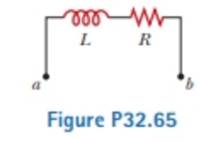
When the current in the portion of the circuit shown in Figure P32.65 is 2.00 A anti increases at a rate of 0.500 A/s, the measured voltage is ΔVab = 9.00 V. When the current is 2.00 A and decreases at the rate of 0.500 A/s. the measured voltage is ΔVab = 5.00 V. Calculate the values of (a) I. and (b) R
Expert Solution & Answer

Trending nowThis is a popular solution!

Students have asked these similar questions
Consider the RLC circuit shown below, where the initial current flowing through the circuit at time t=0 is I_0 = 5, and the initial charge on the capacitor at time t=0 is Q_0 = 2. The components have values of R = 100 ohms, L = 5H, and C = 1/450,500 F.
Write a differential equation for Q(t), the charge across the capacitor, assuming the voltage source V(t)=0.
An initially uncharged capacitor with a capacitance of C = 5.00 µF is connected in series with a resistor with a resistance of R = 4.5 k. If this series combination of circuit elements is attached to an ideal battery with an emf of Ɛ = 450 V by means of a switch S that is closed at time t = 0, then answer the following questions. (a) What is the time constant of this circuit? (b) How long will it take for the capacitor to reach 75% of its final charge? (c) What is the final charge on the capacitor?
A capacitor and a resistor are connected in series across anAC generator, as shown in Figure CQ21.17. After the switchis closed, which of the following statements is true? (a) Thevoltage across the capacitor lags the current by 90°. (b) Thevoltage across the resistor is out of phase with the current.
(c) The voltage across the capacitor leads the current by 90°.(d) The current decreases as the frequency of the generatoris increased, but its peak voltage remains the same. (e) Noneof these
Chapter 32 Solutions
Physics for Scientists and Engineers, Technology Update (No access codes included)
Ch. 32 - A coil with zero resistance has its ends labeled a...Ch. 32 - Prob. 32.2QQCh. 32 - Prob. 32.3QQCh. 32 - Prob. 32.4QQCh. 32 - (i) At an instant of time during the oscillations...Ch. 32 - Prob. 32.1OQCh. 32 - Prob. 32.2OQCh. 32 - Prob. 32.3OQCh. 32 - In Figure OQ32.4, the switch is left in position a...Ch. 32 - Prob. 32.5OQ
Ch. 32 - Prob. 32.6OQCh. 32 - Prob. 32.7OQCh. 32 - Prob. 32.1CQCh. 32 - Prob. 32.2CQCh. 32 - A switch controls the current in a circuit that...Ch. 32 - Prob. 32.4CQCh. 32 - Prob. 32.5CQCh. 32 - Prob. 32.6CQCh. 32 - The open switch in Figure CQ32.7 is thrown closed...Ch. 32 - After the switch is dosed in the LC circuit shown...Ch. 32 - Prob. 32.9CQCh. 32 - Discuss the similarities between the energy stored...Ch. 32 - Prob. 32.1PCh. 32 - Prob. 32.2PCh. 32 - Prob. 32.3PCh. 32 - Prob. 32.4PCh. 32 - An emf of 24.0 mV Ls induced in a 500-turn coil...Ch. 32 - Prob. 32.6PCh. 32 - Prob. 32.7PCh. 32 - Prob. 32.8PCh. 32 - Prob. 32.9PCh. 32 - Prob. 32.10PCh. 32 - Prob. 32.11PCh. 32 - A toroid has a major radius R and a minor radius r...Ch. 32 - Prob. 32.13PCh. 32 - Prob. 32.14PCh. 32 - Prob. 32.15PCh. 32 - Prob. 32.16PCh. 32 - Prob. 32.17PCh. 32 - Prob. 32.18PCh. 32 - Prob. 32.19PCh. 32 - When the switch in Figure P32.18 is closed, the...Ch. 32 - Prob. 32.21PCh. 32 - Show that i = Iiet/ is a solution of the...Ch. 32 - Prob. 32.23PCh. 32 - Consider the circuit in Figure P32.18, taking =...Ch. 32 - Prob. 32.25PCh. 32 - The switch in Figure P31.15 is open for t 0 and...Ch. 32 - Prob. 32.27PCh. 32 - Prob. 32.28PCh. 32 - Prob. 32.29PCh. 32 - Two ideal inductors, L1 and L2, have zero internal...Ch. 32 - Prob. 32.31PCh. 32 - Prob. 32.32PCh. 32 - Prob. 32.33PCh. 32 - Prob. 32.34PCh. 32 - Prob. 32.35PCh. 32 - Complete the calculation in Example 31.3 by...Ch. 32 - Prob. 32.37PCh. 32 - A flat coil of wire has an inductance of 40.0 mH...Ch. 32 - Prob. 32.39PCh. 32 - Prob. 32.40PCh. 32 - Prob. 32.41PCh. 32 - Prob. 32.42PCh. 32 - Prob. 32.43PCh. 32 - Prob. 32.44PCh. 32 - Prob. 32.45PCh. 32 - Prob. 32.46PCh. 32 - In the circuit of Figure P31.29, the battery emf...Ch. 32 - A 1.05-H inductor is connected in series with a...Ch. 32 - A 1.00-F capacitor is charged by a 40.0-V power...Ch. 32 - Calculate the inductance of an LC circuit that...Ch. 32 - An LC circuit consists of a 20.0-mH inductor and a...Ch. 32 - Prob. 32.52PCh. 32 - Prob. 32.53PCh. 32 - Prob. 32.54PCh. 32 - An LC circuit like the one in Figure CQ32.8...Ch. 32 - Show that Equation 32.28 in the text Ls Kirchhoffs...Ch. 32 - In Figure 31.15, let R = 7.60 , L = 2.20 mH, and C...Ch. 32 - Consider an LC circuit in which L = 500 mH and C=...Ch. 32 - Electrical oscillations are initiated in a series...Ch. 32 - Review. Consider a capacitor with vacuum between...Ch. 32 - Prob. 32.61APCh. 32 - An inductor having inductance I. and a capacitor...Ch. 32 - A capacitor in a series LC circuit has an initial...Ch. 32 - Prob. 32.64APCh. 32 - When the current in the portion of the circuit...Ch. 32 - At the moment t = 0, a 24.0-V battery is connected...Ch. 32 - Prob. 32.67APCh. 32 - Prob. 32.68APCh. 32 - Prob. 32.69APCh. 32 - At t = 0, the open switch in Figure P31.46 is...Ch. 32 - Prob. 32.71APCh. 32 - Prob. 32.72APCh. 32 - Review. A novel method of storing energy has been...Ch. 32 - Prob. 32.74APCh. 32 - Review. The use of superconductors has been...Ch. 32 - Review. A fundamental property of a type 1...Ch. 32 - Prob. 32.77APCh. 32 - In earlier times when many households received...Ch. 32 - Assume the magnitude of the magnetic field outside...Ch. 32 - Prob. 32.80CPCh. 32 - To prevent damage from arcing in an electric...Ch. 32 - One application of an RL circuit is the generation...Ch. 32 - Prob. 32.83CP
Knowledge Booster


Learn more about
Need a deep-dive on the concept behind this application? Look no further. Learn more about this topic, physics and related others by exploring similar questions and additional content below.Similar questions
- In the RC circuit shown in Figure P29.78, an ideal battery with emf and internal resistance r is connected to capacitor C. The switch S is initially open and the capacitor is uncharged. At t = 0, the switch is closed. a. Determine the charge q on the capacitor at time t. b. Find the current in the branch be at time t. What is the current as t goes to infinity?arrow_forwardFigure P29.84 shows a circuit that consists of two identical emf devices. If R1 = R2 = R and the switch is closed, find an expression (in terms of R and ) for the current I that is in the branch from point a to b.arrow_forward(a) What is the resistance of a lightbulb that uses an average power of 75.0 W when connected to a 60.0-Hz power source having a maximum voltage of 170 V? (b) What If? What is the resistance of a 100-W lightbulb?arrow_forward
- Consider a series RC circuit as in Figure P28.38 for which R = 1.00 M, C = 5.00 F, and = 30.0 V. Find (a) the time constant of the circuit and (b) the maximum charge on the capacitor after the switch is thrown closed. (c) Find the current in the resistor 10.0 s after the switch is closed.arrow_forwardTo get the maximum current, the connection should be in parallel. If you create a parallel connection with 30V DC source and three resistors with R1 = 50Ω, R2 = 75Ω, and R3 = 100Ω, how do you calculate for the total current (IT) and the current flowing in each resistor (I1, I2, I3), and the total voltage (VT) and the voltage across each resistor (V1, V2, V3)? How do you also determine the power dissipated by each resistor (P1, P2, P3) and by the whole circuit (PT)??arrow_forwardTo get the minimum current, the connection should be in series. If you create a series connection with 30V DC source and three resistors with R1 = 50Ω, R2 = 75Ω, and R3 = 100Ω, how do you calculate for the total current (IT) and the current flowing in each resistor (I1, I2, I3), and the total voltage (VT) and the voltage across each resistor (V1, V2, V3)? How do you also determine the power dissipated by each resistor (P1, P2, P3) and by the whole circuit (PT)??arrow_forward
- A 190 Ω resistor is connected to an AC source with E0 = 5.00 V a. What is the peak current through the resistor if the emf frequency is 100 Hz? b. What is the peak current through the resistor if the emf frequency is 100 kHz?arrow_forwardThe peak current through a resistor is 2.0 A. What is the peak current ifa. The resistance R is doubled?b. The peak emf ε0 is doubled?c. The frequency f is doubled?arrow_forwardYou connect a battery, resistor, and capacitor as in (Figure 1), where E = 46.0 V, C = 5.00 μF, and R = 130 Ω. The switch S is closed at t = 0. When the voltage across the capacitor is 8.00 VV, what is the magnitude of the current in the circuit? At what time tt after the switch is closed is the voltage across the capacitor 8.00 V? When the voltage across the capacitor is 8.00 V, at what rate is energy being stored in the capacitor?arrow_forward
- The current through a 50-Q resistor is I = 0.80 sin (240 t). What is the rms current (in A)?arrow_forward(a) What is the resistance of a lightbulb that uses an average power of 40.0 W when connected to a 60.0-Hz power source having a maximum voltage of 170 V? _________ Ω (b) What is the resistance of a 60.0-W lightbulb? (Assume the lightbulb uses an average power of 60.0 W when connected to a power source having a maximum voltage of 170 V.) _________ Ωarrow_forward(a) What is the resistance of a lightbulb that uses an average power of 60.0 W when connected to a 60.0-Hz power source having a maximum voltage of 170 V?(b) What is the resistance of a 150-W lightbulb? (Assume the lightbulb uses an average power of 150 W when connected to a power source having a maximum voltage of 170 V.)arrow_forward
arrow_back_ios
SEE MORE QUESTIONS
arrow_forward_ios
Recommended textbooks for you
 College PhysicsPhysicsISBN:9781305952300Author:Raymond A. Serway, Chris VuillePublisher:Cengage Learning
 Physics for Scientists and Engineers with Modern ...PhysicsISBN:9781337553292Author:Raymond A. Serway, John W. JewettPublisher:Cengage Learning
 College PhysicsPhysicsISBN:9781285737027Author:Raymond A. Serway, Chris VuillePublisher:Cengage Learning
 Physics for Scientists and Engineers: Foundations...PhysicsISBN:9781133939146Author:Katz, Debora M.Publisher:Cengage Learning
 Physics for Scientists and Engineers, Technology ...PhysicsISBN:9781305116399Author:Raymond A. Serway, John W. JewettPublisher:Cengage Learning
 Principles of Physics: A Calculus-Based TextPhysicsISBN:9781133104261Author:Raymond A. Serway, John W. JewettPublisher:Cengage Learning
College Physics
Physics
ISBN:9781305952300
Author:Raymond A. Serway, Chris Vuille
Publisher:Cengage Learning
Physics for Scientists and Engineers with Modern ...
Physics
ISBN:9781337553292
Author:Raymond A. Serway, John W. Jewett
Publisher:Cengage Learning
College Physics
Physics
ISBN:9781285737027
Author:Raymond A. Serway, Chris Vuille
Publisher:Cengage Learning
Physics for Scientists and Engineers: Foundations...
Physics
ISBN:9781133939146
Author:Katz, Debora M.
Publisher:Cengage Learning
Physics for Scientists and Engineers, Technology ...
Physics
ISBN:9781305116399
Author:Raymond A. Serway, John W. Jewett
Publisher:Cengage Learning
Principles of Physics: A Calculus-Based Text
Physics
ISBN:9781133104261
Author:Raymond A. Serway, John W. Jewett
Publisher:Cengage Learning
DC Series circuits explained - The basics working principle; Author: The Engineering Mindset;https://www.youtube.com/watch?v=VV6tZ3Aqfuc;License: Standard YouTube License, CC-BY