
Videos
(a)
The graph of
(a)
Answer to Problem 44PQ
Plot for the induced emf in coil

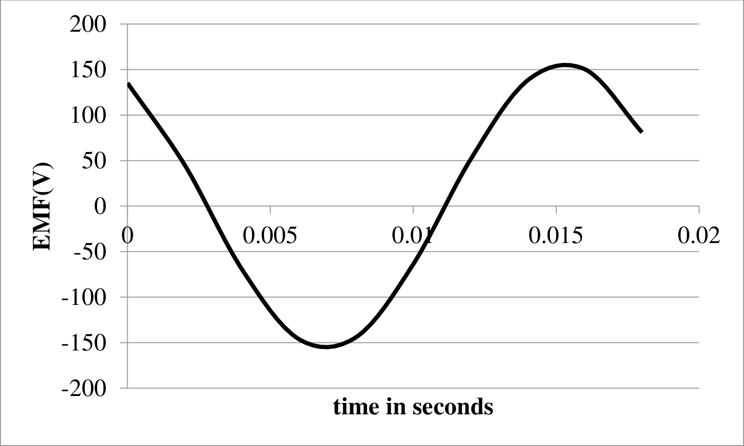
Plot for the induced emf in coil 2 is shown below.
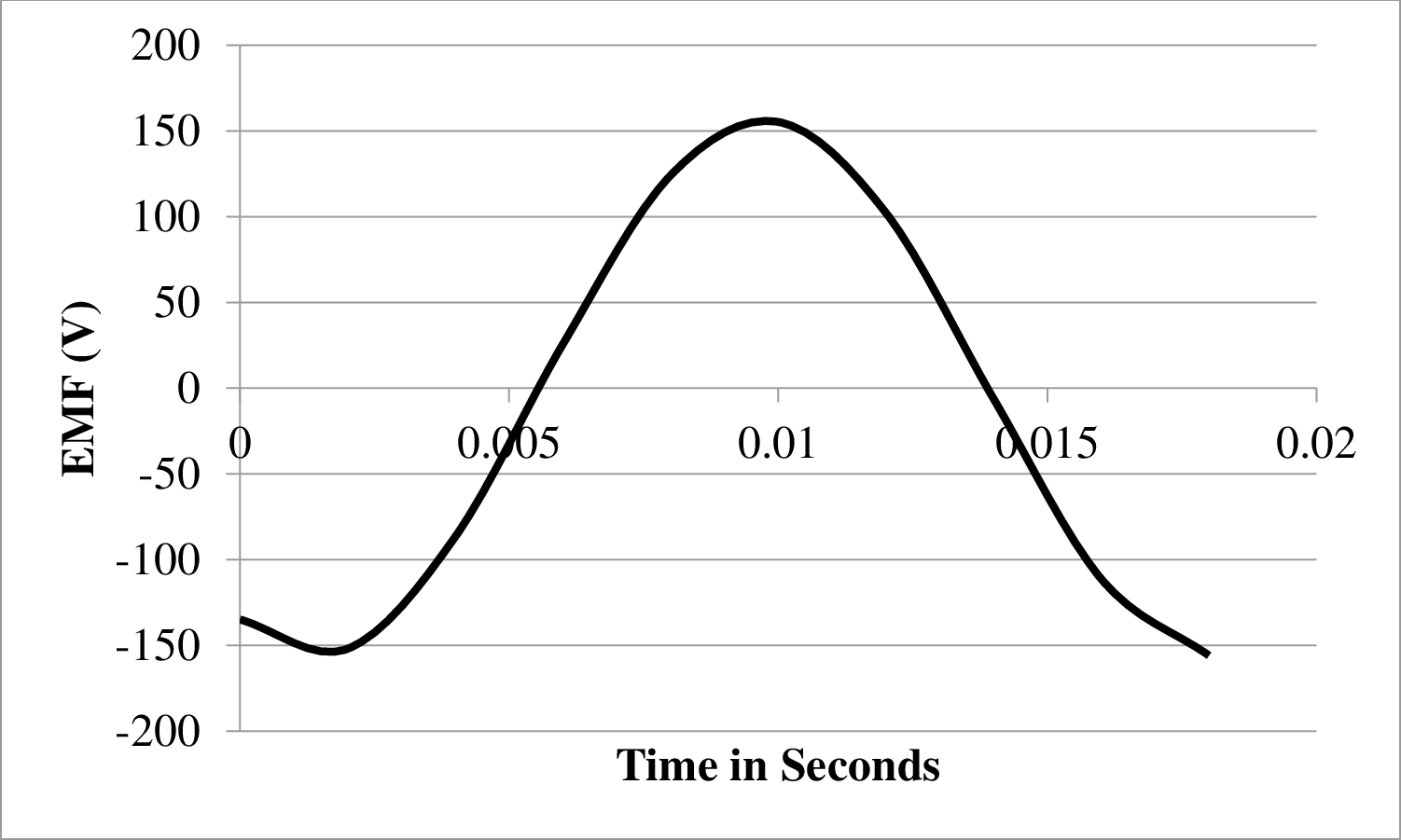
Plot for induced emf in coil

Explanation of Solution
As it is known that a three phase generator has
Therefore, a phase a difference of
Write the expression to calculate the induced emf in the coil.
Here,
Write the expression to calculate the peak value of emf.
Here,
Write the expression for the angular frequency.
Here,
Let the coil
Substitute
Write the Equation for the emf of coil
Convert degree in to radian
Write the expression for induced emf in coil
Substitute
Convert degree in to radian
Write the expression for induced emf in coil
Substitute
Calculate the peak emf
Substitute
Conclusion:
Calculate the angular frequency.
Substitute
Calculate the equation of emf for coil
Substitute
Calculate the equation of emf for coil
Substitute
Calculate the equation of emf for coil
Substitute
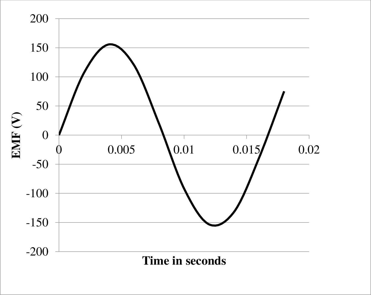
Draw the table to plot the graph at different time interval.
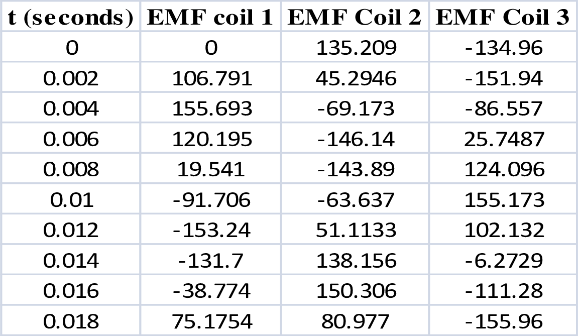
Plot for the induced emf in coil
Plot for the induced emf in coil 2 is shown below.

Plot for induced emf in coil
(b)
The ways in which a three phase generator is better than a one phase generator.
(b)
Answer to Problem 44PQ
The three phase generator has higher efficiency and higher power factor compared to a one phase generator which is its major advantage over one phase generator.
Explanation of Solution
The advantage of three phase generator over a one phase generator are as follows.
- 1. The power output of a three phase generator is constant whereas the power generated by a one phase generator is pulsating that it is not constant and behaves in an alternating manner.
- 2. The three phase generator has higher power factor as compared to one phase generator.
- 3. The three phase generator has much higher efficiency as compared to the one phase motor.
Want to see more full solutions like this?
Chapter 32 Solutions
EBK PHYSICS FOR SCIENTISTS AND ENGINEER


- When a wire carries an AC current with a known frequency, you can use a Rogowski coil to determine the amplitude Imax of the current without disconnecting the wire to shunt the current through a meter. The Rogowski coil, shown in Figure P23.8, simply clips around the wire. It consists of a toroidal conductor wrapped around a circular return cord. Let n represent the number of turns in the toroid per unit distance along it. Let A represent the cross-sectional area of the toroid. Let I(t) = Imax sin t represent the current to be measured. (a) Show that the amplitude of the emf induced in the Rogowski coil is Emax=0nAImax. (b) Explain why the wire carrying the unknown current need not be at the center of the Rogowski coil and why the coil will not respond to nearby currents that it does not enclose. Figure P23.8arrow_forwardA 75-turn, 10.0 cm diameter coil rotates at an angular velocity of 8.00 radius in a 1.25 T field, starting with the plane of the coil parallel to the field. (a) What is the peak emf? (b) At what time is the peak emf first reached? (c) At what time is the emf first at its meet negative? (d) What is the period of the AC voltage output?arrow_forward(a) If the emf of a coil rotating in a magnetic field is zero at t = 0, and increases to its first peak at t = 0.100 ms, what is the angular velocity of the coil? (b) At what time will its next maximum occur? (c) What is the period of the output? (d) When is the output first one-fourth at its maximum? (e) When is it next one-fourth at its maximum?arrow_forward
- A coil with a self-inductance of 3.0 H and a resistance of 100 2 carries a steady current of 2.0 A. (a) What is the energy stored in the magnetic field of the coil? (b) What is the energy per second dissipated in the resistance of the coil?arrow_forward19. A loop of wire (Area of loop = 0.02 m², plane of loop in x/y plane) enters a region of space with a uniform B-field (100 T) oriented in the positive z direction. What is the induced emf for the loop as it traverses the field? A. 2 v B. 0.2 v C. 0.001 V D. O varrow_forwardAs a way of determining the inductance of a coil used in a research project, a student first connects the coil to a 12.0-V battery and measures a current of 0.630 A. The student then connects the coil to a 24.0-V (rms) 60.0-Hz generator and measures an rms current of 0.370 A. a. Find the resistance of the coil. b. Find the inductance of the coil.arrow_forward
- Exp. No. Stator Voltage Control of an Induction Motor using PWM The objective: The objective of this experiment is to present the voltage control of induction motor. The theory: Stator Voltage Control is a method used to control the speed of Fan laad an Induction Motor. The speed of a three phase induction motor can be varied by varying the supply voltage. n na n Speed n As we already know that the torque developed is proportional to the square of the supply voltage and the slip at the maximum torque is independent of the supply voltage. The variation in the supply voltage does not alter the synchronous speed of the motor. Soo Procedure: 1. Using Matlab-Simulink, connect the circuit shown above, Connect the circuit shown above with Vdc=400V and Tm=10N.m. 2. To control the IGBTS, a PWM, 6-pulse and three arms will be used. 3. Let the carrier frequency = 2kHz. 4. Let the modulation index inside the PWM = m in order to vary it from the command window of Matlab. 5. Vary the modulation…arrow_forwardAn LC-circuit like the one shown in the figure contains an75.0-mH inductor and a 20-μF capacitor that initially carries a 200-μCcharge. The switch is thrown closed at t=0 seconds. a. Find the angular frequency (in rad/sec) of the resultingoscillation. A. 258 rad/sec B. 816 rad/sec C. 133 rad/sec D. 413 rad/sec b. Find the frequency (in Hertz) of the resulting oscillation. A. 41.1 Hz B. 130 Hz C. 21.2 Hz D. 65.8 Hz c. What is the formula for the charge (in Coulombs) on the capacitor, Q(t), as a function of time.A. Q(t) = 7.50x10^-6 cos(21.2t) B. Q(t) = 413x10^-6 cos(130t) C. Q(t) = 200x10^-6 cos(816t) D. Q(t) = 133x10^-6 cos(39.8t) Please answer all the parts c). show all the work neatly and every step in detail. Thanks! Answers for part a and b are given in bold.arrow_forwardAn American traveler in China carries a transformer to convert China's standard 220 V to 120 V so that she can use some small appliances on her trip. a. What is the ratio of turns in the primary and secondary coils of her transformer? Np/Ns = b. What is the ratio of input to output current? Iin/Iout = c. How could a Chinese person traveling in the United States use this same transformer to power her 220 V appliances from 120 V?arrow_forward
- b. Derive an expression for the magnitude of the induced emf in the loop as a function of time for the interval t = 0 s to t = 6 s. c. Calculate the magnitude of the induced current at time t = 3 s. d. Sketch a graph of the induced current in the loop as a function of time from t = 0 s to t = 18 s. Show the direction of the induced current on the loop depicted in the Figure above. e. Calculate the total energy dissipated in the loop during the first 6 seconds.arrow_forwardL Given the LC circuit above, with L = The switch is closed at time t = 0. 50mH, C = 5µF, Qo= 3 x 10-³ C. a. Find the capacitor's charge at t = 3ms. b. What are the capacitor's and inductor's energy at that time?arrow_forwardQ01arrow_forward
 Physics for Scientists and Engineers: Foundations...PhysicsISBN:9781133939146Author:Katz, Debora M.Publisher:Cengage Learning
 College PhysicsPhysicsISBN:9781938168000Author:Paul Peter Urone, Roger HinrichsPublisher:OpenStax College
 Principles of Physics: A Calculus-Based TextPhysicsISBN:9781133104261Author:Raymond A. Serway, John W. JewettPublisher:Cengage Learning
 College PhysicsPhysicsISBN:9781285737027Author:Raymond A. Serway, Chris VuillePublisher:Cengage Learning
 College PhysicsPhysicsISBN:9781305952300Author:Raymond A. Serway, Chris VuillePublisher:Cengage Learning
 Physics for Scientists and EngineersPhysicsISBN:9781337553278Author:Raymond A. Serway, John W. JewettPublisher:Cengage Learning