Videos
(a)
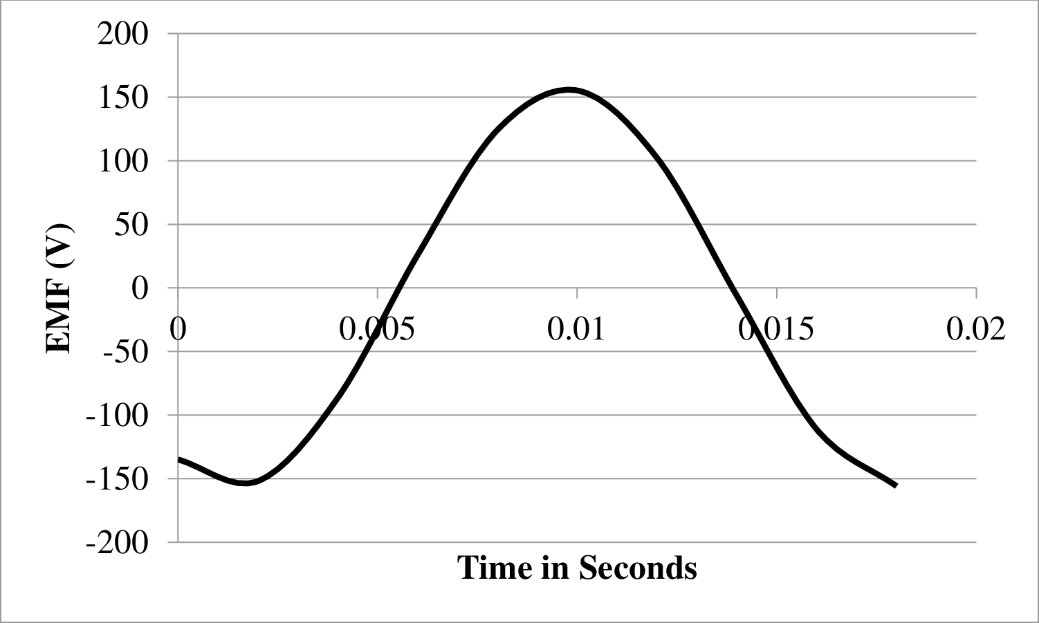
The graph of
(a)
Answer to Problem 44PQ
Plot for the induced emf in coil

Plot for the induced emf in coil 2 is shown below.
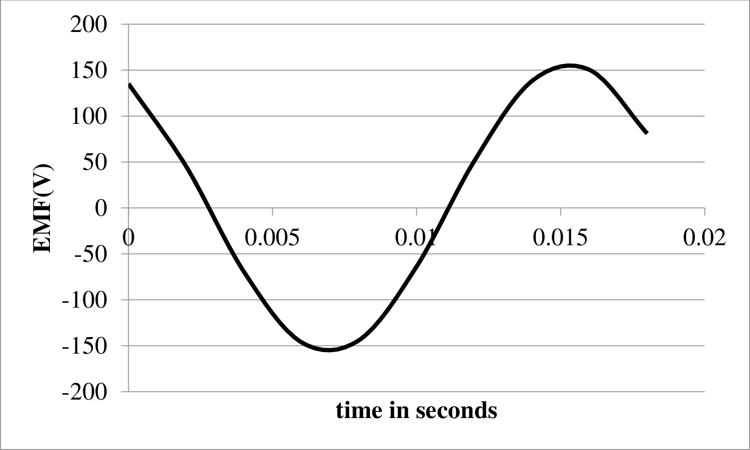
Plot for induced emf in coil

Explanation of Solution
As it is known that a three phase generator has
Therefore, a phase a difference of
Write the expression to calculate the induced emf in the coil.
Here,
Write the expression to calculate the peak value of emf.
Here,
Write the expression for the angular frequency.
Here,
Let the coil
Substitute
Write the Equation for the emf of coil
Convert degree in to radian
Write the expression for induced emf in coil
Substitute
Convert degree in to radian
Write the expression for induced emf in coil
Substitute
Calculate the peak emf
Substitute
Conclusion:
Calculate the angular frequency.
Substitute
Calculate the equation of emf for coil
Substitute
Calculate the equation of emf for coil
Substitute
Calculate the equation of emf for coil
Substitute
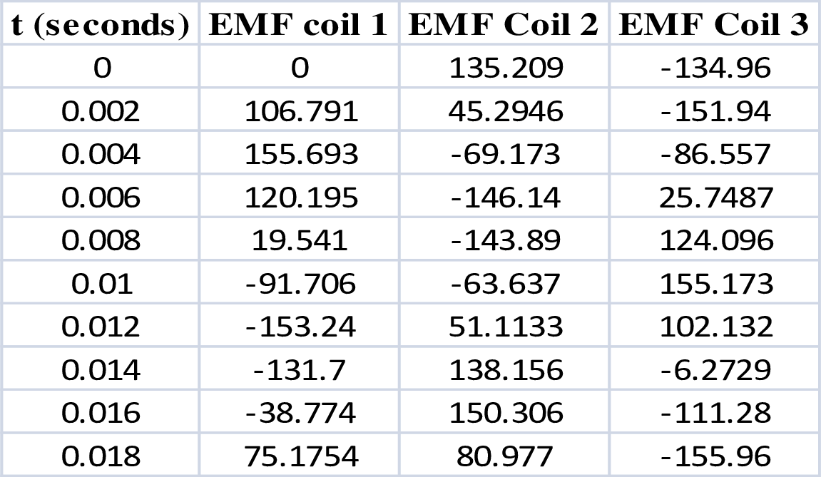
Draw the table to plot the graph at different time interval.
Plot for the induced emf in coil
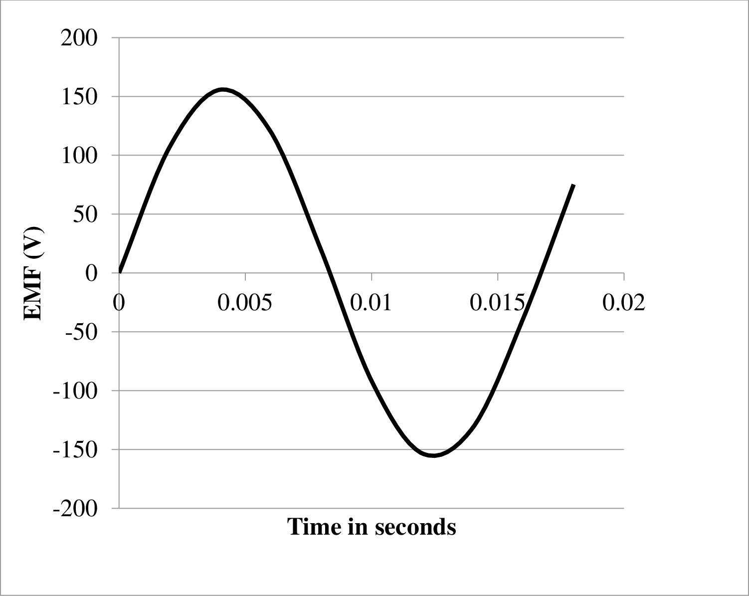
Plot for the induced emf in coil 2 is shown below.

Plot for induced emf in coil
(b)
The ways in which a three phase generator is better than a one phase generator.
(b)
Answer to Problem 44PQ
The three phase generator has higher efficiency and higher power factor compared to a one phase generator which is its major advantage over one phase generator.
Explanation of Solution
The advantage of three phase generator over a one phase generator are as follows.
- 1. The power output of a three phase generator is constant whereas the power generated by a one phase generator is pulsating that it is not constant and behaves in an alternating manner.
- 2. The three phase generator has higher power factor as compared to one phase generator.
- 3. The three phase generator has much higher efficiency as compared to the one phase motor.
Want to see more full solutions like this?
Chapter 32 Solutions
Physics for Scientists and Engineers: Foundations and Connections, Advance Edition, Volume 2


- When a wire carries an AC current with a known frequency, you can use a Rogowski coil to determine the amplitude Imax of the current without disconnecting the wire to shunt the current through a meter. The Rogowski coil, shown in Figure P23.8, simply clips around the wire. It consists of a toroidal conductor wrapped around a circular return cord. Let n represent the number of turns in the toroid per unit distance along it. Let A represent the cross-sectional area of the toroid. Let I(t) = Imax sin t represent the current to be measured. (a) Show that the amplitude of the emf induced in the Rogowski coil is Emax=0nAImax. (b) Explain why the wire carrying the unknown current need not be at the center of the Rogowski coil and why the coil will not respond to nearby currents that it does not enclose. Figure P23.8arrow_forwardA bar magnet is dropped through a loop of wire as shown in Figure P32.64. a. What is the direction of the induced current as the magnet is approaching the loop, as viewed from above where the magnet begins? b. What is the direction of the induced current after the magnet falls through and is receding from the loop, as viewed from above where the magnet began? FIGURE P32.64arrow_forwardA rectangular loop of length L and width W is placed in a uniform magnetic field B with its plane perpendicular to the field (Fig. P32.7). Determine the time-averaged induced emf if the loop rotatas with constant angular velocity through an angle of 180 around an axis passing through the loops center a. perpendicular to the loop and b. parallel to its width.arrow_forward
- Two coaxial cables of length with radii a and b are carrying currents in opposite directions as shown in Figure P33.78. Determine the inductance of the system. Hint: Use Ampres law to write an expression for the magnetic field in the region between the cables, a distance r from the axis of the cables. Then calculate the magnetic flux through a narrow rectangular region between the cables such that the Field is perpendicular to the area everywhere. FIGURE P33.78arrow_forwardAn N-turn square coil with side and resistance R is pulled to the right at constant speed v in the presence of a uniform magnetic field B acting perpendicular to the coil as shown in Figure P30.43. At t = 0, the right side of the coil has just departed the right edge of the field. At time t, the left side of the coil enters the region where B = 0. In terms of the quantities N, B, , v, and R, find symbolic expressions for (a) the magnitude of the induced emf in the loop during the time interval from t = 0 to t, (b) the magnitude of the induced current in the coil, (c) the power delivered to the coil, and (d) the force required to remove the coil from the field. (e) What is the direction of the induced current in the loop? (f) What is the direction of the magnetic force on the loop while it is being pulled out of the field? Figure P30.43arrow_forwardFigure P32.6 shows three situations involving a single circular loop of wire. For each case, decide whether an emf is induced in the circular loop. Explain your reasoning. Case 1: The loop lies in the plane of the page near a solenoid with its long axis perpendicular to the page. The solenoids magnetic field is increasing. Case 2: A solenoid carries a constant current. The loop falls straight down inside the solenoid. Case 3: A solenoid carries a constant current. The loop is wrapped around a ball. The ball and loop roll along the inside of the solenoid.arrow_forward
 Physics for Scientists and Engineers: Foundations...PhysicsISBN:9781133939146Author:Katz, Debora M.Publisher:Cengage Learning
 Principles of Physics: A Calculus-Based TextPhysicsISBN:9781133104261Author:Raymond A. Serway, John W. JewettPublisher:Cengage Learning
 Physics for Scientists and EngineersPhysicsISBN:9781337553278Author:Raymond A. Serway, John W. JewettPublisher:Cengage Learning
 Physics for Scientists and Engineers with Modern ...PhysicsISBN:9781337553292Author:Raymond A. Serway, John W. JewettPublisher:Cengage Learning
 College PhysicsPhysicsISBN:9781938168000Author:Paul Peter Urone, Roger HinrichsPublisher:OpenStax College
 Physics for Scientists and Engineers, Technology ...PhysicsISBN:9781305116399Author:Raymond A. Serway, John W. JewettPublisher:Cengage Learning