
PHYSICS FOR SCI.AND ENGR W/WEBASSIGN
10th Edition
ISBN: 9781337888462
Author: SERWAY
Publisher: CENGAGE L
expand_more
expand_more
format_list_bulleted
Videos
Textbook Question
Chapter 32, Problem 4P
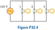
Figure P32.4 shows three lightbulbs connected to a 120-V AC (rms) household supply voltage. Bulbs 1 and 2 have a power rating of 150 W, and bulb 3 has a 100-W rating. Find (a) the rms current in each bulb and (b) the resistance of each bulb. (c) What is the total resistance of the combination of the three lightbulbs?
Figure P32.4
Expert Solution & Answer

Trending nowThis is a popular solution!

Students have asked these similar questions
As shown three lightbulbs connected to a 120-V AC (rms) household supply voltage. Bulbs 1 and 2 have a power rating of 150 W, and bulb 3 has a 100-W rating. Find (a) the rms current in each bulb and (b) the resistance of each bulb. (c) What is the total resistance of the combination of the three lightbulbs?
At its highest temperature, a space heater has a resistance of 25.5 Q when it is plugged into a wall outlet that supplies a peak
voltage of 162.6 V sinusoidally at 60 Hz. What is the average power output P of the space heater?
P =
W
A 190 Ω resistor is connected to an AC source with E0 = 5.00 V
a. What is the peak current through the resistor if the emf frequency is 100 Hz?
b. What is the peak current through the resistor if the emf frequency is 100 kHz?
Chapter 32 Solutions
PHYSICS FOR SCI.AND ENGR W/WEBASSIGN
Ch. 32.2 - Consider the voltage phasor in Figure 32.4, shown...Ch. 32.3 - Consider the AC circuit in Figure 32.8. The...Ch. 32.4 - Consider the AC circuit in Figure 32.11. The...Ch. 32.4 - Consider the AC circuit in Figure 32.12. The...Ch. 32.5 - Label each part of Figure 32.16, (a), (b), and...Ch. 32.6 - An AC source drives an RLC circuit with a fixed...Ch. 32.7 - What is the impedance of a series RLC circuit at...Ch. 32 - (a) What is the resistance of a lightbulb that...Ch. 32 - A certain lightbulb is rated at 60.0 W when...Ch. 32 - The current in the circuit shown in Figure P32.3...
Ch. 32 - Figure P32.4 shows three lightbulbs connected to a...Ch. 32 - In the AC circuit shown in Figure P32.3, R = 70.0 ...Ch. 32 - In a purely inductive AC circuit as shown in...Ch. 32 - Prob. 7PCh. 32 - A 20.0-mH inductor is connected to a North...Ch. 32 - An AC source has an output rms voltage of 78.0 V...Ch. 32 - Review. Determine the maximum magnetic flux...Ch. 32 - A 1.00-mF capacitor is connected to a North...Ch. 32 - An AC source with an output rms voltage of 86.0 V...Ch. 32 - What is the maximum current in a 2.20-F capacitor...Ch. 32 - A capacitor C is connected to a power supply that...Ch. 32 - In addition to phasor diagrams showing voltages...Ch. 32 - An AC source with Vmax = 150 V and f = 50.0 Hz is...Ch. 32 - You are working in a factory and have been tasked...Ch. 32 - Prob. 18PCh. 32 - An RLC circuit consists of a 150- resistor, a...Ch. 32 - A 60.0-ft resistor is connected in series with a...Ch. 32 - A series RLC circuit has a resistance of 45.0 and...Ch. 32 - Prob. 22PCh. 32 - A series RLC circuit has a resistance of 22.0 and...Ch. 32 - An AC voltage of the form v = 90.0 sin 350t, where...Ch. 32 - The LC circuit of a radar transmitter oscillates...Ch. 32 - A series RLC circuit has components with the...Ch. 32 - You wish to build a series RLC circuit for a...Ch. 32 - A 10.0- resistor, 10.0-mH inductor, and 100-F...Ch. 32 - A resistor R, inductor L, and capacitor C are...Ch. 32 - The primary coil of a transformer has N1 = 350...Ch. 32 - A person is working near the secondary of a...Ch. 32 - A transmission line that has a resistance per unit...Ch. 32 - Prob. 33APCh. 32 - A 400- resistor, an inductor, and a capacitor are...Ch. 32 - Energy is to be transmitted over a pair of copper...Ch. 32 - Energy is to be transmitted over a pair of copper...Ch. 32 - A transformer may be used to provide maximum power...Ch. 32 - Show that the rms value for the sawtooth voltage...Ch. 32 - Marie Cornu, a physicist at the Polytechnic...Ch. 32 - A series RLC circuit has resonance angular...Ch. 32 - Review. One insulated conductor from a household...Ch. 32 - (a) Sketch a graph of the phase angle for an RLC...Ch. 32 - Prob. 43APCh. 32 - Review. In the circuit shown in Figure P32.44,...Ch. 32 - You have decided to build your own speaker system...Ch. 32 - A series RLC circuit is operating at 2.00 103 Hz....Ch. 32 - You are trying to become a member of the Physics...Ch. 32 - A series RLC circuit in which R = l.00 , L = 1.00...Ch. 32 - The resistor in Figure P32.49 represents the...Ch. 32 - An 80.0- resistor and a 200-mH inductor are...Ch. 32 - Prob. 51CP
Knowledge Booster


Learn more about
Need a deep-dive on the concept behind this application? Look no further. Learn more about this topic, physics and related others by exploring similar questions and additional content below.Similar questions
- (a) What is the resistance of a light bulb that uses an average power of 75.0 W when connected to a 60.0-Hz power source having a maximum voltage of 170. V? (b) What is the resistance of a 100.-W lightbulb?arrow_forwardPlease box answers.arrow_forwardAn AC power supply produces a maximum voltage of Vmax= 100 V. This power supply is connected to a resistor R= 24.00, and the current and resistor voltage is measured with an ideal AC ammeter and voltmeter. An ideal ammeter has zero resistance, and an ideal voltmeter has infinite resistance. What is the reading on, a. The ammeter b. The voltmeterarrow_forward
- The figure below shows three lightbulbs connected to a 120-V AC (rms) household supply voltage. Bulbs 1 and 2 have a power rating of 75 W, and bulb 3 has a 40-W rating. 120 V 1 2 3 (a) Find the rms current in each bulb. Ibulb 1 = A Ibulb 2 = A Ibulb 3 = A (b) Find the resistance of each bulb. Ω Rbulb 1 = Rbulb 2 = Ω Rbulb 3 2 i (c) What is the total resistance of the combination of the three lightbulbs? Ωarrow_forward150 0 and C = 40_µF in a (charging) RC-series circuit with a 8 V power source. What is the Suppose R maximum charge on the capacitor? What is the charge on the capacitor after 0.0011 s?, What is the charge after 2.5 time constants? %3D %3D 5. max charge A. 0.0004616 C D. 0.00032 C E. 0.0003308 C F. 0.0005613_C В. 0.0005623 C C. 0.000514 C 6. charge after 0.0011_s 0.00002812 C 0.00005323 C C. 0.00006192_C D. 0.0000536 C E. 0.00009703 C F. 0.00009941 C A. В. /-1 7. charge after 2.5 time constants A. 0.0004973 C D. 0.0001524_C 0.0002937 C C. 0.0002599_C 0.000584 C F. 0.0001862 C B. E. IZG 000 100arrow_forwardTwo lightbulbs are designed for use with an ac voltage (rms) of 120 V. One lightbulb is rated at 60 W and the other at 30 W. Which bulb, if either, has the greater filament resistance? O Both bulbs have the same resistance since they are subject to the same voltage. O The 60 W bulb. O The 30 W bulb.arrow_forward
- The capacitor in the circuit shown is fully charged by a 24 V battery. The switch is closed at t = 0. At sometime after the switch is closed, the voltage across the capacitor is measured to be 10 V. What is the current in the circuit at this time, in Ampere? C = 3.0 µF, and R = 2.0 02. Your answer needs to have 2 significant figures, including the negative sign in your answer if needed. Do not include the positive sign if the answer is positive. No unit is needed in your answer, it is already given in the question statement. Cilarrow_forwardP1arrow_forwardAnswer is Barrow_forward
- The capacitor in the circuit shown below is initially uncharged. The switch is closed at t = 0 s. AVbattery = 24 V, C = 3.0 μF, and R = 2.0 Q. At sometime after the switch is closed, the voltage across the capacitor is measured to be 10 V. What is the current in the circuit at this time, in Ampere? Your answer needs to have 2 significant figures, including the negative sign in your answer if needed. Do not include the positive sign if the answer is positive. No unit is needed in your answer, it is already given in the question statement.arrow_forwardIf known, R1 = 2.7 Ω, R2 = 4.3 Ω, R3 = 5 Ω, R4 = 3 Ω, R5 =15 Ω, and the source voltage Vs =41 Volts, determine the total resistance of the circuit, voltage at each resistor and the strength of the electric current through each resistor.arrow_forwardThe rms current in a 50-Ω resistor is 0.42 A. What is the peak value of the voltage across this resistor?arrow_forward
arrow_back_ios
SEE MORE QUESTIONS
arrow_forward_ios
Recommended textbooks for you
 Physics for Scientists and EngineersPhysicsISBN:9781337553278Author:Raymond A. Serway, John W. JewettPublisher:Cengage Learning
 Physics for Scientists and Engineers with Modern ...PhysicsISBN:9781337553292Author:Raymond A. Serway, John W. JewettPublisher:Cengage Learning
 College PhysicsPhysicsISBN:9781305952300Author:Raymond A. Serway, Chris VuillePublisher:Cengage Learning
 College PhysicsPhysicsISBN:9781285737027Author:Raymond A. Serway, Chris VuillePublisher:Cengage Learning
 Physics for Scientists and Engineers: Foundations...PhysicsISBN:9781133939146Author:Katz, Debora M.Publisher:Cengage Learning
 Physics for Scientists and Engineers, Technology ...PhysicsISBN:9781305116399Author:Raymond A. Serway, John W. JewettPublisher:Cengage Learning
Physics for Scientists and Engineers
Physics
ISBN:9781337553278
Author:Raymond A. Serway, John W. Jewett
Publisher:Cengage Learning
Physics for Scientists and Engineers with Modern ...
Physics
ISBN:9781337553292
Author:Raymond A. Serway, John W. Jewett
Publisher:Cengage Learning
College Physics
Physics
ISBN:9781305952300
Author:Raymond A. Serway, Chris Vuille
Publisher:Cengage Learning
College Physics
Physics
ISBN:9781285737027
Author:Raymond A. Serway, Chris Vuille
Publisher:Cengage Learning
Physics for Scientists and Engineers: Foundations...
Physics
ISBN:9781133939146
Author:Katz, Debora M.
Publisher:Cengage Learning
Physics for Scientists and Engineers, Technology ...
Physics
ISBN:9781305116399
Author:Raymond A. Serway, John W. Jewett
Publisher:Cengage Learning
Introduction To Alternating Current; Author: Tutorials Point (India) Ltd;https://www.youtube.com/watch?v=0m142qAZZpE;License: Standard YouTube License, CC-BY