Bundle: Physics for Scientists and Engineers, Technology Update, 9th Loose-leaf Version + WebAssign Printed Access Card, Multi-Term
9th Edition
ISBN: 9781305714892
Author: Raymond A. Serway, John W. Jewett
Publisher: Cengage Learning
expand_more
expand_more
format_list_bulleted
Videos
Textbook Question
Chapter 33, Problem 33.3P
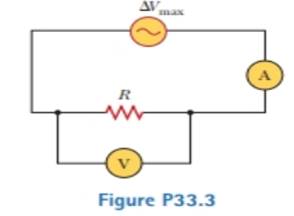
An AC power supply produces a maximum voltage ΔVmax = 100 V. This power supply is connected to a resistor H = 24.0 Ω, and the current and resistor voltage are measured with an ideal AC ammeter and voltmeter as shown in Figure P33.3. An ideal ammeter has zero resistance, and an ideal voltmeter has infinite resistance. What is the reading on (a) the ammeter and (b) the voltmeter?
Expert Solution & Answer

Trending nowThis is a popular solution!

Students have asked these similar questions
An AC power supply produces a maximum voltage of Vmax= 100 V. This power supply is connected to a resistor R= 24.00, and the current and resistor voltage is measured with an ideal AC ammeter and voltmeter. An ideal ammeter has
zero resistance, and an ideal voltmeter has infinite resistance. What is the reading on,
a. The ammeter
b. The voltmeter
An RC circuit, hooked up to a battery as shown in the figure, starts with an uncharged capacitor.
The resistance in the circuit is R = 681.0 2 the capacitor has capacitance of C = 88.0 µF and the
battery maintains the emf of ɛ = 15.0 V. The switch is closed at time t = 0.0 s and the capacitor
begins to charge.
R
What is the time constant for this circuit?
Submit Answer Tries 0/99
What is the charge on the capacitor after the switch has been closed for t = 7.01×10⁻² s?
Submit Answer Tries 0/99
What is the current through the circuit after the switch has been closed for t = 7.01×10⁻² s?
Submit Answer Tries 0/99
What is the voltage across the capacitor after the switch has been closed for t = 7.01x10⁻² s?
Submit Answer Tries 0/99
b c d
Chapter 33 Solutions
Bundle: Physics for Scientists and Engineers, Technology Update, 9th Loose-leaf Version + WebAssign Printed Access Card, Multi-Term
Ch. 33 - Consider the voltage phasor in Figure 32.4, shown...Ch. 33 - Consider the AC circuit in Figure 32.8. The...Ch. 33 - Consider the AC circuit in Figure 32.11. The...Ch. 33 - Consider the AC circuit in Figure 32.12. The...Ch. 33 - Label each part of Figure 32.16, (a), (b), and...Ch. 33 - An AC source drives an RLC circuit with a fixed...Ch. 33 - What is the impedance of a series RLC circuit at...Ch. 33 - An inductor and a resistor are connected in series...Ch. 33 - (i) When a particular inductor is connected to a...Ch. 33 - A capacitor and a resistor are connected in series...
Ch. 33 - Prob. 33.4OQCh. 33 - Prob. 33.5OQCh. 33 - A sinusoidally varying potential difference has...Ch. 33 - A series RLCcircuit contains a 20.0- resistor, a...Ch. 33 - A resistor, a capacitor, and an inductor are...Ch. 33 - (a) Why does a capacitor act as a short circuit at...Ch. 33 - What is the plia.se angle in a series RLC circuit...Ch. 33 - Prob. 33.11OQCh. 33 - A 6.00-V battery is connected across the primary...Ch. 33 - Do AC ammeters and voltmeters read (a)...Ch. 33 - (a) Explain how the quality factor is related to...Ch. 33 - (a) Explain how the mnemonic ELI the ICE man can...Ch. 33 - Why is the sum of the maximum voltages across each...Ch. 33 - (a) Does the phase angle in an RLC series circuit...Ch. 33 - Prob. 33.5CQCh. 33 - As shown in Figure CQ33.6, a person pulls a vacuum...Ch. 33 - Prob. 33.7CQCh. 33 - Will a transformer operate if a battery is used...Ch. 33 - Prob. 33.9CQCh. 33 - Prob. 33.10CQCh. 33 - When an AC source is connected across a 12.0-...Ch. 33 - (a) What is the resistance of a lightbulb that...Ch. 33 - An AC power supply produces a maximum voltage Vmax...Ch. 33 - A certain lightbulb is rated at 60.0 W when...Ch. 33 - The current in the circuit shown in Figure P32.3...Ch. 33 - In the AC circuit shown in Figure P32.3, R = 70.0 ...Ch. 33 - An audio amplifier, represented by the AC I source...Ch. 33 - Figure P32.4 shows three lightbulbs connected to a...Ch. 33 - An inductor has a .54.0- reactance when connected...Ch. 33 - In a purely inductive AC circuit as shown in...Ch. 33 - Prob. 33.11PCh. 33 - An inductor is connected to an AC power supply...Ch. 33 - An AC source has an output rms voltage of 78.0 V...Ch. 33 - A 20.0-mH inductor is connected to a North...Ch. 33 - Review. Determine the maximum magnetic flux...Ch. 33 - The output voltage of an AC source is given by v =...Ch. 33 - A 1.00-mF capacitor is connected to a North...Ch. 33 - An AC source with an output rms voltage of 86.0 V...Ch. 33 - (a) For what frequencies does a 22.0-F capacitor...Ch. 33 - A source delivers an AC voltage of the form =...Ch. 33 - What maximum current is delivered by an AC source...Ch. 33 - A capacitor C is connected to a power supply that...Ch. 33 - What is the maximum current in a 2.20-F capacitor...Ch. 33 - An AC source with Vmax = 150 V and f = 50.0 Hz is...Ch. 33 - In addition to phasor diagrams showing voltages...Ch. 33 - A sinusoidal voltage = 40.0 sin 100t, where is...Ch. 33 - A series AC circuit contains a resistor, an...Ch. 33 - At what frequency does the inductive reactance of...Ch. 33 - An RLC circuit consists of a 150- resistor, a...Ch. 33 - Prob. 33.30PCh. 33 - An inductor (L = 400 mH), a capacitor (C = 4.43...Ch. 33 - A 60.0-ft resistor is connected in series with a...Ch. 33 - Review. In an RLC series circuit that includes a...Ch. 33 - Prob. 33.34PCh. 33 - A series RLC circuit has a resistance of 45.0 and...Ch. 33 - An AC voltage of the form = 100 sin 1 000t, where...Ch. 33 - A series RLC circuit has a resistance of 22.0 and...Ch. 33 - An AC voltage of the form v = 90.0 sin 350t, where...Ch. 33 - ln a certain series RLC circuit, Irms = 9.00 A,...Ch. 33 - Prob. 33.40PCh. 33 - Prob. 33.41PCh. 33 - A series RLC circuit has components with the...Ch. 33 - An RLC circuit is used in a radio to tune into an...Ch. 33 - The LC circuit of a radar transmitter oscillates...Ch. 33 - A 10.0- resistor, 10.0-mH inductor, and 100-F...Ch. 33 - A resistor R, inductor L, and capacitor C are...Ch. 33 - Review. A radar transmitter contains an LC circuit...Ch. 33 - A step-down transformer is used for recharging the...Ch. 33 - The primary coil of a transformer has N1 = 350...Ch. 33 - A transmission line that has a resistance per unit...Ch. 33 - In the transformer shown in Figure P33.51, the...Ch. 33 - A person is working near the secondary of a...Ch. 33 - The RC high-pass filter shown in Figure P33.53 has...Ch. 33 - Consider the RC high-pass filler circuit shown in...Ch. 33 - Prob. 33.55PCh. 33 - Consider the Filter circuit shown in Figure...Ch. 33 - A step-up transformer is designed to have an...Ch. 33 - Prob. 33.58APCh. 33 - Review. The voltage phasor diagram for a certain...Ch. 33 - Prob. 33.60APCh. 33 - Energy is to be transmitted over a pair of copper...Ch. 33 - Energy is to be transmitted over a pair of copper...Ch. 33 - A 400- resistor, an inductor, and a capacitor are...Ch. 33 - Show that the rms value for the sawtooth voltage...Ch. 33 - A transformer may be used to provide maximum power...Ch. 33 - A capacitor, a coil, and two resistors of equal...Ch. 33 - Marie Cornu, a physicist at the Polytechnic...Ch. 33 - A series RLC circuit has resonance angular...Ch. 33 - Review. One insulated conductor from a household...Ch. 33 - (a) Sketch a graph of the phase angle for an RLC...Ch. 33 - In Figure P33.71, find the rms current delivered...Ch. 33 - Review. In the circuit shown in Figure P32.44,...Ch. 33 - Prob. 33.73APCh. 33 - A series RLC circuit is operating at 2.00 103 Hz....Ch. 33 - A series RLC circuit consists of an 8.00-...Ch. 33 - A series RLC circuit in which R = l.00 , L = 1.00...Ch. 33 - The resistor in Figure P32.49 represents the...Ch. 33 - An 80.0- resistor and a 200-mH inductor are...Ch. 33 - Prob. 33.79CPCh. 33 - P33.80a shows a parallel RLC circuit. The...Ch. 33 - Prob. 33.81CP
Knowledge Booster


Learn more about
Need a deep-dive on the concept behind this application? Look no further. Learn more about this topic, physics and related others by exploring similar questions and additional content below.Similar questions
- (a) What is the resistance of a light bulb that uses an average power of 75.0 W when connected to a 60.0-Hz power source having a maximum voltage of 170. V? (b) What is the resistance of a 100.-W lightbulb?arrow_forwardIn an RC series circuit, the EMF, E = 8.1 Volts, resistance = 1.40 MQ and the capacitance = 10.0 µF. Calculate the maximum charge possible on the capacitor in μC. %3D Use 1 decimal place in your answer.arrow_forwardi1arrow_forward
- An RC (resistor + capacitor) circuit will have an exponential voltage response of the form v(t) = A + B e -t/RC where A and B are constants that express the final voltage and the difference between the initial voltage and the final voltage, respectively. Given R = 10 kΩ and C = 0.1 µF, a starting voltage of 5 Volts and an ending voltage of 0 Volts, what will the voltage be at t = 1 ms? At what time will the voltage be 0.5 Volts?arrow_forwardAn electric circuit consists of two emf sources with negligible internal resistance, three resistors, and a voltage meter (V) as represented in the picture above. The voltage meter has infinite resistance and displays the voltage V_ab= V_a - V_b between the points a and b in the circuit. What is the magnitude and direction (towards or away from point b) of the current in the 9.00 ohm resistor ? What is the voltage difference V_ab the voltmeter displays?arrow_forwardThe series circuit at the right depicts two resistors connected to a voltage source. The voltage source (AV tot) has an unknown voltage. The resistor values are 26 ≤ (R₁) and 27 (R₂), and the current in the wire at all points is 0.77 A. What is the voltage of the battery? Answer: V. AV tot R₁ R₂arrow_forward
- d,e and f ?arrow_forwardP1arrow_forwardThe emf source, ε=4.5 V, of the circuit shown in the figure has negligible internal resistance. The resistors have resistances R1=2 Ω and R2=4.7 Ω. The capacitor has a capacitance C=4.9 μF. Determine the time constant τ, in units of microseconds, for charging the capacitor. What is the charge Q on the capacitor in units of microcoulomb?arrow_forward
- The internal circuitry of a heart defibrillator includes a 7.42 μF parallel plate capacitor. When Hawkeye Pierce applies the defibrillator's paddles across a patient's torso, the result is a series RC circuit. 0.049 If the capacitor's voltage declines from 10.7 kV to 213 V in 0.049 s, what must be the resistance (in 2) of the circuit through the patient's torso?arrow_forwardA small circuit consists of a resistor in series with a capacitor, as shown. The capacitor stores 79.2 mJ of energy after a ?bat=10.0 V battery has been connected to the circuit for a long time. Then, the capacitor discharges half of this stored energy in exactly1.28 s when the battery is removed and replaced by a ??=1.10×10^3 Ω load. Determine the value of the capacitance C1 in microfarads and resistance R1 in ohms. Please solve for both C1 and R1, thanks!arrow_forwardA 190 Ω resistor is connected to an AC source with E0 = 5.00 V a. What is the peak current through the resistor if the emf frequency is 100 Hz? b. What is the peak current through the resistor if the emf frequency is 100 kHz?arrow_forward
arrow_back_ios
SEE MORE QUESTIONS
arrow_forward_ios
Recommended textbooks for you
 Principles of Physics: A Calculus-Based TextPhysicsISBN:9781133104261Author:Raymond A. Serway, John W. JewettPublisher:Cengage Learning
 College PhysicsPhysicsISBN:9781305952300Author:Raymond A. Serway, Chris VuillePublisher:Cengage Learning
 Physics for Scientists and Engineers with Modern ...PhysicsISBN:9781337553292Author:Raymond A. Serway, John W. JewettPublisher:Cengage Learning
 Physics for Scientists and Engineers, Technology ...PhysicsISBN:9781305116399Author:Raymond A. Serway, John W. JewettPublisher:Cengage Learning
Principles of Physics: A Calculus-Based Text
Physics
ISBN:9781133104261
Author:Raymond A. Serway, John W. Jewett
Publisher:Cengage Learning
College Physics
Physics
ISBN:9781305952300
Author:Raymond A. Serway, Chris Vuille
Publisher:Cengage Learning
Physics for Scientists and Engineers with Modern ...
Physics
ISBN:9781337553292
Author:Raymond A. Serway, John W. Jewett
Publisher:Cengage Learning
Physics for Scientists and Engineers, Technology ...
Physics
ISBN:9781305116399
Author:Raymond A. Serway, John W. Jewett
Publisher:Cengage Learning
DC Series circuits explained - The basics working principle; Author: The Engineering Mindset;https://www.youtube.com/watch?v=VV6tZ3Aqfuc;License: Standard YouTube License, CC-BY