Videos
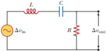
The resistor in Figure P32.49 represents the midrange speaker in a three-speaker system. Assume its resistance to be constant at 8.00 Ω. The source represents an audio amplifier producing signals of uniform amplitude ΔVmax = 10.0 V at all audio frequencies. The inductor and capacitor are to function as a band-pass filter with
Figure P32.49
(a)
Answer to Problem 33.77CP
Explanation of Solution
Given info: The value of resistance is
Formula to calculate the output potential difference is,
Here,
Formula to calculate the input potential difference is,
Here,
Divide equation (1) and equation (1).
Formula to calculate the inductive reactance of the circuit is,
Here,
Formula to calculate the inductive reactance of the circuit is,
Here,
Formula to calculate the impedance of the circuit is,
Here,
Substitute
At low frequency that is
Substitute
Substitute
Solve the equation further,
Divide the equation by
At high frequency that is
Substitute
Substitute
Solve the equation further,
Subtract the equation (5) and equation (6) to find the value of
Conclusion:
Therefore, the required value of inductance
(b)
Answer to Problem 33.77CP
Explanation of Solution
Given info: The value of resistance is
The equation (6) is given as,
Substitute
Conclusion:
Therefore, the required value of capacitance
(c)
Answer to Problem 33.77CP
Explanation of Solution
Given info: The value of resistance is
The value
At resonance condition,
Substitute
Conclusion:
Therefore, the maximum value of the ratio
(d)
Answer to Problem 33.77CP
Explanation of Solution
Given info: The value of resistance is
Since the ratio
Formula to calculate the resonance frequency is,
Substitute
Conclusion:
Therefore, the frequency
(e)
Answer to Problem 33.77CP
Explanation of Solution
Given info: The value of resistance is
Formula to calculate the phase shift between
At
Substitute
At
Substitute
At
Substitute
Conclusion:
Therefore, the phase shift between
(f)
Answer to Problem 33.77CP
Explanation of Solution
Given info: The value of resistance is
Formula to calculate the rms output voltage is,
Formula to calculate the power deliver to the speaker is,
Substitute
For low frequency
Substitute
Substitute
For resonance frequency
Substitute
Substitute
Conclusion:
Therefore, the average power transferred to the speaker at
(g)
Answer to Problem 33.77CP
Explanation of Solution
Given info: The value of resistance is
Formula to calculate the quality factor is,
Substitute
Conclusion:
Therefore, the quality factor of the circuit is
Want to see more full solutions like this?
Chapter 33 Solutions
Physics For Scientists And Engineers, Volume 2, Technology Update


- The RC high-pass filter shown in Figure P33.53 has a resistance R = 0.500 and a capacitance C = 613 F. What is the ratio of the amplitude of the output voltage to that of the input voltage for this filter for a source frequency of 600 Hz?arrow_forwardIn the AC circuit shown in Figure P32.3, R = 70.0 and the output voltage of the AC source is Vmax sin t. (a) If VR = 0.250 Vmax for the first time at t = 0.0100 s, what is the angular frequency of the source? (b) What is the next value of t for which VR = 0.250 Vmax? Figure P32.6 Problem 3 and 5.arrow_forwardAn PLC series circuit with R=600 , L = 30 mH. and c=0.050F is driven by an ac source whose frequency and voltage amplitude are 500 Hz and 50 V, respectively, (a) What is the impedance of the circuit? (b) What is the amplitude of the current in the circuit? (c) What is the phase angle between the emf of the source and the current?arrow_forward
- An RLC series circuit with R = 600 Ω , L = 30 mH, and C = 0.050μF is driven by an ac source whose frequency and voltage amplitude are 500 Hz and 50 V,respectively. (a) What is the impedance of the circuit? (b) What is the amplitude of the current in the circuit? (c) What is the phase angle between the emf of the source and the current?arrow_forward(a) What is the resonant frequency (in Hz) of a resistor, capacitor, and inductor connected in series if R = 120 Ω, L = 2.6 H, and C = 5.8 µF? (b) If this combination is connected to a source with a voltage amplitude of 100 V operating at the resonant frequency, what is the average power output of the source (in W)? (c) What is the Q of the circuit? (d) What is the bandwidth of the circuit (in rad/s)?arrow_forwardVP31.7.2 An L-R-C series circuit has a source with voltage amplitude 35.0 V and angular frequency 1.30 × 10³ rad/s. The resistance is 275 Ω, the inductance is 82.3 mH, and the capacitance is 1.10 μF1. Find (a) the inductive and capacitive reactances, (b) the phase angle, and (c) the power factor.arrow_forward
- An RLC series circuit with R = 600 Ω, L = 30 mH,and C = 0.050µF is driven by an ac source whosefrequency and voltage amplitude are 500 Hz and 50 V,respectively. (a) What is the impedance of the circuit? (b)What is the amplitude of the current in the circuit? (c) Whatis the phase angle between the emf of the source and the current?arrow_forwardAn AC source operating at 60. Hz with a maximum voltage of170 V is connected in series with a resistor (R = 1.2 kΩ) anda capacitor (C 5 2.5 µF). (a) What is the maximum value ofthe current in the circuit? (b) What are the maximum valuesof the potential difference across the resistor and the capacitor?(c) When the current is zero, what are the magnitudesof the potential difference across the resistor, the capacitor,and the AC source? How much charge is on the capacitor atthis instant? (d) When the current is at a maximum, what arethe magnitudes of the potential differences across the resistor,the capacitor, and the AC source? How much charge is on thecapacitor at this instant?arrow_forwardAn AC source operating at 60 Hz with a maximum voltage of 170 V is connected in series with a resistor (R = 1.2 kV) and a capacitor (C = 2.5 µF). (a) What is the maximum value of the current in the circuit? (b) What are the maximum values of the potential difference across the resistor and the capacitor? (c) When the current is zero, what are the magnitudes of the potential difference across the resistor, the capacitor, and the AC source? How much charge is on the capacitor at this instant? (d) When the current is at a maximum, what are the magnitudes of the potential differences across the resistor, the capacitor, and the AC source? How much charge is on the capacitor at this instant?arrow_forward
- A high-pass filter consists of a 1.63 μF capacitor in series with a 90.0 Ω resistor. The circuit is driven by an AC source with a peak voltage of 5.25 V . a. What is the crossover frequency fc? b. What is VR when f=1/2fc? c. What is VR when f =fc?arrow_forwardA sinusoidal voltage where Vmax = 100.0 V and a frequency of 60 Hz is applied to a series RLC circuit with L = 186 mH, C = 88.4 µF, and R = 30.0 Ω. (a) What is the capacitive reactance? (b) What is the inductive reactance? (c) What is the impedance of the circuit? (d) What is the rms voltage? (e) At what frequency would this combination of inductor, L, and capacitor, C, be at resonance?arrow_forwardA sinusoidal voltage Δv = 35.0 sin(100t), where Δv is in volts and t is in seconds, is applied to a series RLC circuit with L = 180 mH, C = 99.0 µF, and R = 67.0 Ω. (a)What is the impedance (in Ω) of the circuit? Ω (b)What is the maximum current (in A)? A (c)Determine the numerical value for ? (in rad/s) in the equation i = Imax sin(?t − ?). rad/s (d)Determine the numerical value for ? (in rad) in the equation i = Imax sin(?t − ?). rad (e)What If? For what value of the inductance (in H) in the circuit would the current lag the voltage by the same angle ? as that found in part (d)? H (f)What would be the maximum current (in A) in the circuit in this case? Aarrow_forward
 Physics for Scientists and EngineersPhysicsISBN:9781337553278Author:Raymond A. Serway, John W. JewettPublisher:Cengage Learning
 Physics for Scientists and Engineers with Modern ...PhysicsISBN:9781337553292Author:Raymond A. Serway, John W. JewettPublisher:Cengage Learning
 Physics for Scientists and Engineers: Foundations...PhysicsISBN:9781133939146Author:Katz, Debora M.Publisher:Cengage Learning
 Physics for Scientists and Engineers, Technology ...PhysicsISBN:9781305116399Author:Raymond A. Serway, John W. JewettPublisher:Cengage Learning