
Vector Mechanics for Engineers: Statics and Dynamics
12th Edition
ISBN: 9781259638091
Author: Ferdinand P. Beer, E. Russell Johnston Jr., David Mazurek, Phillip J. Cornwell, Brian Self
Publisher: McGraw-Hill Education
expand_more
expand_more
format_list_bulleted
Concept explainers
Videos
Textbook Question
Chapter 3.3, Problem 3.94P
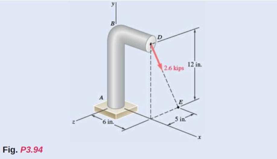
A 2.6-kip force is applied at point D of the cast-iron post shown. Replace that force with an equivalent force-couple system at the center A of the base section.
Expert Solution & Answer
Want to see the full answer?
Check out a sample textbook solution
Students have asked these similar questions
A 2.6-kip force is applied at point D of the cast-iron post shown.Replace that force with an equivalent force-couple system at the center A of the base section.
A 2.6-kip force is applied at point D of the cast-iron post shown. Replace that force with an equivalent force-couple system at the center A of the base section.
A 260-lb force is applied at A to the rolled-steel section shown.Replace that force with an equivalent force-couple system at the center C of the section.
Chapter 3 Solutions
Vector Mechanics for Engineers: Statics and Dynamics
Ch. 3.1 - A foot valve for a pneumatic system is hinged at...Ch. 3.1 - 3.2A foot valve for a pneumatic system is hinged...Ch. 3.1 - It is known that a vertical force of 200 lb is...Ch. 3.1 - A 300-N force is applied at A as shown. Determine...Ch. 3.1 - A 300-N force is applied at A as shown. Determine...Ch. 3.1 - An 8-lb force P is applied to a shift lever....Ch. 3.1 - For the shift lever shown, determine the magnitude...Ch. 3.1 - An 11-lb force P is applied to a shift lever. The...Ch. 3.1 - Rod AB is held in place by the cord AC. Knowing...Ch. 3.1 - Rod AB is held in place by the cord AC. Knowing...
Ch. 3.1 - 3.11 and 3.12The tailgate of a car is supported by...Ch. 3.1 - 3.11 and 3.12The tailgate of a car is supported by...Ch. 3.1 - 3.13 and 3.14It is known that the connecting rod...Ch. 3.1 - 3.13 and 3.14It is known that the connecting rod...Ch. 3.1 - Form the vector product P1 P2 and use the result...Ch. 3.1 - The vectors P and Q are two adjacent sides of a...Ch. 3.1 - A plane contains the vectors A and B. Determine...Ch. 3.1 - A line passes through the points (4 m, 3 m) and (2...Ch. 3.1 - Prob. 3.19PCh. 3.1 - Determine the moment about the origin O of the...Ch. 3.1 - Before the trunk of a large tree is felled, cables...Ch. 3.1 - The 12-ft boom AB has a fixed end A. A steel cable...Ch. 3.1 - A 200-N force is applied as shown to the bracket...Ch. 3.1 - A force P of magnitude 200 N acts along the...Ch. 3.1 - A 6-ft-long fishing rod AB is securely anchored in...Ch. 3.1 - A precast concrete wall section is temporarily...Ch. 3.1 - In Prob. 3.22, determine the perpendicular...Ch. 3.1 - In Prob. 3.23, determine the perpendicular...Ch. 3.1 - In Prob. 3.24, determine the perpendicular...Ch. 3.1 - In Prob. 3.25, determine the perpendicular...Ch. 3.1 - In Prob. 3.25, determine the perpendicular...Ch. 3.1 - In Prob. 3.26, determine the perpendicular...Ch. 3.1 - In Prob. 3.26, determine the perpendicular...Ch. 3.1 - Determine the value of a that minimizes the...Ch. 3.2 - Given the vectors P = 2i + j + 2k, Q = 3i + 4j ...Ch. 3.2 - Form the scalar product B C and use the result...Ch. 3.2 - Three cables are attached to the top of the tower...Ch. 3.2 - Three cables are attached to the top of the tower...Ch. 3.2 - Knowing that the tension in cable AC is 280 lb,...Ch. 3.2 - Prob. 3.40PCh. 3.2 - Ropes AB and BC are two of the ropes used to...Ch. 3.2 - Prob. 3.42PCh. 3.2 - The 20-in. tube AB can slide along a horizontal...Ch. 3.2 - Solve Prob. 3.43 for the position corresponding to...Ch. 3.2 - Determine the volume of the parallelepiped of Fig....Ch. 3.2 - Given the vectors P = 3i + 2j + k, Q = 5i + j 2k,...Ch. 3.2 - A crane is oriented so that the end of the 25-m...Ch. 3.2 - 3.48The 25-m crane boom AO lies in the yz plane....Ch. 3.2 - To loosen a frozen valve, a force F with a...Ch. 3.2 - 3.50When a force F is applied to the handle of the...Ch. 3.2 - The 0.61 1.00-m lid ABCD of a storage bin is...Ch. 3.2 - 3.52The 0.61 1.00-m lid ABCD of a storage bin is...Ch. 3.2 - A farmer uses cables and winch pullers B and E to...Ch. 3.2 - Solve Prob. 3.53 when the tension in cable AB is...Ch. 3.2 - A force P of magnitude 520 lb acts on the frame...Ch. 3.2 - 3.56A force P acts on the frame shown at point E....Ch. 3.2 - The frame ACD is hinged at A and D and is...Ch. 3.2 - In Prob. 3.57, determine the moment about the...Ch. 3.2 - The triangular plate ABC is supported by...Ch. 3.2 - 3.60The triangular plate ABC is supported by...Ch. 3.2 - A regular tetrahedron has six edges of length a. A...Ch. 3.2 - Prob. 3.62PCh. 3.2 - Prob. 3.63PCh. 3.2 - In Prob. 3.55, determine the perpendicular...Ch. 3.2 - In Prob. 3.56, determine the perpendicular...Ch. 3.2 - In Prob. 3.57, determine the perpendicular...Ch. 3.2 - In Prob. 3.58, determine the perpendicular...Ch. 3.2 - In Prob. 3.59, determine the perpendicular...Ch. 3.2 - In Prob. 3.60, determine the perpendicular...Ch. 3.3 - Two 80-N forces are applied as shown to the...Ch. 3.3 - Two parallel 60-N forces are applied as shown to...Ch. 3.3 - A multiple-drilling machine is used to drill...Ch. 3.3 - Four pegs of the same diameter are attached to a...Ch. 3.3 - Prob. 3.74PCh. 3.3 - The shafts of an angle drive are acted upon by the...Ch. 3.3 - If P = 0 in the figure, replace the two remaining...Ch. 3.3 - 3.77If P = 20 lb in the figure, replace the three...Ch. 3.3 - The two couples shown are to be replaced with a...Ch. 3.3 - Solve part a of Prob. 3.78, assuming that two 15-N...Ch. 3.3 - Shafts A and B connect the gear box to the wheel...Ch. 3.3 - A 500-N force is applied to a bent plate as shown....Ch. 3.3 - Prob. 3.82PCh. 3.3 - Prob. 3.83PCh. 3.3 - A 30-lb vertical force P is applied at A to the...Ch. 3.3 - A worker tries to move a rock by applying a 360-N...Ch. 3.3 - A worker tries to move a rock by applying a 360-N...Ch. 3.3 - The shearing forces exerted on the cross section...Ch. 3.3 - Knowing that = 60, replace the force and couple...Ch. 3.3 - Three control rods attached to a lever ABC exert...Ch. 3.3 - A rectangular plate is acted upon by the force and...Ch. 3.3 - While tapping a hole, a machinist applies the...Ch. 3.3 - Prob. 3.92PCh. 3.3 - Replace the 250-kN force P with an equivalent...Ch. 3.3 - A 2.6-kip force is applied at point D of the...Ch. 3.3 - Prob. 3.95PCh. 3.3 - To keep a door closed, a wooden stick is wedged...Ch. 3.3 - A 46-lb force F and a 2120-lbin. couple M are...Ch. 3.3 - Prob. 3.98PCh. 3.3 - Prob. 3.99PCh. 3.3 - Prob. 3.100PCh. 3.4 - 3.101A 4-m-long beam is subjected to a variety of...Ch. 3.4 - A 4-m-long beam is loaded as shown. Determine the...Ch. 3.4 - Determine the single equivalent force and the...Ch. 3.4 - Five separate force-couple systems act at the...Ch. 3.4 - The weights of two children sitting at ends A and...Ch. 3.4 - Three stage lights are mounted on a pipe as shown....Ch. 3.4 - A beam supports three loads of given magnitude and...Ch. 3.4 - A 6 12-in. plate is subjected to four loads as...Ch. 3.4 - Gear C is rigidly attached to arm AB. If the...Ch. 3.4 - To test the strength of a 625 500-mm suitcase,...Ch. 3.4 - Prob. 3.111PCh. 3.4 - Prob. 3.112PCh. 3.4 - The roof of a building frame is subjected to the...Ch. 3.4 - Prob. 3.114PCh. 3.4 - A couple M and the three forces shown are applied...Ch. 3.4 - A machine component is subjected to the forces and...Ch. 3.4 - Prob. 3.117PCh. 3.4 - As follower AB rolls along the surface of member...Ch. 3.4 - A machine component is subjected to the forces...Ch. 3.4 - Two 150-mm-diameter pulleys are mounted on line...Ch. 3.4 - As an adjustable brace BC is used to bring a wall...Ch. 3.4 - In order to unscrew the tapped faucet A, a plumber...Ch. 3.4 - Prob. 3.123PCh. 3.4 - Four forces are applied to the machine component...Ch. 3.4 - A blade held in a brace is used to tighten a screw...Ch. 3.4 - A mechanic uses a crowfoot wrench to loosen a bolt...Ch. 3.4 - Four horizontal forces act on a vertical...Ch. 3.4 - Determine the magnitude of the force P for which...Ch. 3.4 - Prob. 3.129PCh. 3.4 - Prob. 3.130PCh. 3.4 - A concrete foundation mat of 5-m radius supports...Ch. 3.4 - Prob. 3.132PCh. 3.4 - Three forces of the same magnitude P act on a cube...Ch. 3.4 - A piece of sheet metal is bent into the shape...Ch. 3.4 - Prob. 3.135PCh. 3.4 - Prob. 3.136PCh. 3.4 - Two bolts at A and B are tightened by applying the...Ch. 3.4 - Two bolts at A and B are tightened by applying the...Ch. 3.4 - Prob. 3.139PCh. 3.4 - Prob. 3.140PCh. 3.4 - Prob. 3.141PCh. 3.4 - Prob. 3.142PCh. 3.4 - Replace the wrench shown with an equivalent system...Ch. 3.4 - Prob. 3.144PCh. 3.4 - Show that a wrench can be replaced with two...Ch. 3.4 - Show that a wrench can be replaced with two...Ch. 3 - A 300-N force P is applied at point A of the bell...Ch. 3 - A winch puller AB is used to straighten a fence...Ch. 3 - A small boat hangs from two davits, one of which...Ch. 3 - Prob. 3.150RPCh. 3 - A single force P acts at C in a direction...Ch. 3 - The 23-in. vertical rod CD is welded to the...Ch. 3 - In a manufacturing operation, three holes are...Ch. 3 - A 260-lb force is applied at A to the rolled-steel...Ch. 3 - The force and couple shown are to be replaced by...Ch. 3 - Prob. 3.156RPCh. 3 - Prob. 3.157RPCh. 3 - While using a pencil sharpener, a student applies...
Knowledge Booster


Learn more about
Need a deep-dive on the concept behind this application? Look no further. Learn more about this topic, mechanical-engineering and related others by exploring similar questions and additional content below.Similar questions
- A 260-lb force is applied at A to the rolled-steel section shown. Replace that force with an equivalent force-couple system at the center C of the section.arrow_forwardA machine component is subjected to the forces shown, each of which is parallel to one of the coordinate axes. Replace these forces with an equivalent force-couple system at A.arrow_forwardA 500-N force is applied to a bent plate as shown. Determine (a) an equivalent force-couple system at B, (b) an equivalent system formedby a vertical force at A and a force at B.arrow_forward
- Two parallel 60-N forces are applied as shown to the corners A and C of a 200-mm square plate. Determine themoment of the couple formed by the two forces (a) by multiplying their magnitude by their perpendicular distance,(b) by resolving each force into horizontal and vertical components and adding the moments of the two resultingcouplesarrow_forwardTwo 150-mm-diameter pulleys are mounted on line shaft AD. The belts at B and C lie in vertical planes parallel to the yz plane. Replace the belt forces shown with an equivalent force-couple system at A.arrow_forwardThe flanged steel cantilever beam with riveted bracket is subjected to the couple and two forces shown, and their effect on the design of the attachment at A must be determined. Replace the two forces and couple by an equivalent couple M and resultant R at A. The couple is positive if counterclockwise, negative if clockwise.arrow_forward
- The tension in the cable attached to the end C of an adjustable boom ABC is 560 lb. Replace the force exerted by the cable at C with an equivalent force-couple system (a) at A, (b) at B.arrow_forwardAn overhead view of a portion of an exercise machine is shown. If the tension in the cable is T = 750 N, determine the equivalent force-couple system at (a) point B and at (b) point O.arrow_forwardThree cables are attached to a bracket as shown. Replace the forces exerted by the cables with an equivalent force-couple system at Aarrow_forward
- The bar AB, which is inclined at the angle to the horizontal, is subjected to the four forces shown. Knowing that these forces have no resultant (neither a force nor a couple), determine P1,P2, and .arrow_forwardIn order to design the foundation for the utility pole shown to the right, replace the system of three applied forces with an equivalent force- couple system applied at point A.arrow_forwardThe tension in cable AB is 17 kN. Replace this force as it acts on point A by an equivalent force-couple system at O. Point B is located at the center of the container top.arrow_forward
arrow_back_ios
SEE MORE QUESTIONS
arrow_forward_ios
Recommended textbooks for you
 International Edition---engineering Mechanics: St...Mechanical EngineeringISBN:9781305501607Author:Andrew Pytel And Jaan KiusalaasPublisher:CENGAGE L
International Edition---engineering Mechanics: St...
Mechanical Engineering
ISBN:9781305501607
Author:Andrew Pytel And Jaan Kiusalaas
Publisher:CENGAGE L
Introduction To Engg Mechanics - Newton's Laws of motion - Kinetics - Kinematics; Author: EzEd Channel;https://www.youtube.com/watch?v=ksmsp9OzAsI;License: Standard YouTube License, CC-BY