
Engineering Mechanics: Statics
8th Edition
ISBN: 9781118807330
Author: James L. Meriam, L. G. Kraige, J. N. Bolton
Publisher: WILEY
expand_more
expand_more
format_list_bulleted
Concept explainers
Videos
Textbook Question
Chapter 3.3, Problem 43P
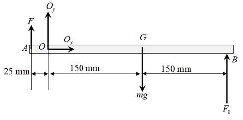
In a procedure to evaluate the strength of the triceps muscle, a person pushes down on a load cell with the palm of his hand as indicated in the figure. If the load-cell reading is 160 N, determine the vertical tensile force F generated by the triceps muscle. The mass of the lower arm is 1.5 kg with mass center at G. State any assumptions.
Expert Solution & Answer
Want to see the full answer?
Check out a sample textbook solution
Students have asked these similar questions
A ladder with a uniform cross-section has a length of 4.80-foot long. It weighs W Ib. It is arranged such that one end is on the ground and the other against a vertical wall. The angle of triction at all contact surtaces is 20 degrees. What is the value of the coefficient of triction? What is f, in terms of variable Na? What is the normal force at A in terms of variable W? Answer in three decimal places
PROBLEM 7: In the figure, μ = 0.30 for the contact of the 80-kg crate and the ground. Pulleys are frictionless. (a) determine the value of θ to move the crate (b) Determine the tensile force (in N) in the rope attached to the crate to move the crate. (c) Determine the smallest force (in N) the man must exert on the rope to move the crate
Two springs, as shown are to carry a load of 90 kN. The spring on the left is the larger spring. Spring specifications are as follows: wire diameter=25 mm, outside coil diameter= 230mm, no. of active coils=8; and wire diameter=20 mm, outside coil diameter= 170mm, no. of active coils=20. Take G= 79 GPa. Determine the force exerted by each spring and the stress induced in each.
Chapter 3 Solutions
Engineering Mechanics: Statics
Ch. 3.3 - In the side view of a 50-lb flat-screen television...Ch. 3.3 - The mass center G of the 1400-kg rear-engine car...Ch. 3.3 - A carpenter carries a 12-lb 2-in. by 4-in. board...Ch. 3.3 - The 450-kg uniform I-beam supports the load shown....Ch. 3.3 - Determine the force P required to maintain the...Ch. 3.3 - The 20-kg homogeneous smooth sphere rests on the...Ch. 3.3 - The 600-lb drum is being hoisted by the lifting...Ch. 3.3 - If the screw B of the wood clamp is tightened so...Ch. 3.3 - Determine the reactions at A and E if P=500 N....Ch. 3.3 - What horizontal force P must a worker exert on the...
Ch. 3.3 - The 20-kg uniform rectangular plate is supported...Ch. 3.3 - The 500-kg uniform beam is subjected to the three...Ch. 3.3 - A former student of mechanics wishes to weigh...Ch. 3.3 - The uniform rectangular body of mass m is placed...Ch. 3.3 - What weight WB will cause the system to be in...Ch. 3.3 - The pair of hooks is designed for the hanging of...Ch. 3.3 - The winch takes in cable at the constant rate of...Ch. 3.3 - To accommodate the rise and fall of the tide, a...Ch. 3.3 - When the 0.05-kg body is in the position shown,...Ch. 3.3 - When the 0.05-kg body is in the position shown,...Ch. 3.3 - When on level ground, the car is placed on four...Ch. 3.3 - Determine the magnitude P of the force required to...Ch. 3.3 - The 180-lb exerciser is beginning to execute some...Ch. 3.3 - Three cables are joined at the junction ring C...Ch. 3.3 - Determine the moment M which the motor must exert...Ch. 3.3 - A bicyclist applies a 40-N force to the brake...Ch. 3.3 - Find the angle of tilt with the horizontal so...Ch. 3.3 - The rack has a mass m=75kg. What moment M must be...Ch. 3.3 - The elements of a wheel-height adjuster for a lawn...Ch. 3.3 - The right-angle uniform slender bar AOB has mass...Ch. 3.3 - Determine the minimum cylinder mass m1 required to...Ch. 3.3 - Cable AB passes over the small ideal pulley C...Ch. 3.3 - A pipe P is being bent by the pipe bender as...Ch. 3.3 - The small slider A is moved along the circular...Ch. 3.3 - The asymmetric simple truss is loaded as shown....Ch. 3.3 - The tailgate OBC is attached to the rear of a...Ch. 3.3 - The indicated location of the center of gravity of...Ch. 3.3 - A uniform ring of mass m and radius r carries an...Ch. 3.3 - Determine the force T required to hold the uniform...Ch. 3.3 - A block placed under the head of the claw hammer...Ch. 3.3 - The uniform slender bar of length 2r and mass m...Ch. 3.3 - The chain binder is used to secure loads of logs,...Ch. 3.3 - In a procedure to evaluate the strength of the...Ch. 3.3 - A woman is holding a 3.6-kg sphere in her hand...Ch. 3.3 - A person is performing slow arm curls with a 10-kg...Ch. 3.3 - The exercise machine is designed with a...Ch. 3.3 - For a given value m1 for the cart mass, determine...Ch. 3.3 - The device shown is used to test automobile-engine...Ch. 3.3 - The portable floor crane in the automotive shop is...Ch. 3.3 - The torsional spring of constant kT=50Nm/rad is...Ch. 3.3 - A torque (moment) of 24Nm is required to turn the...Ch. 3.3 - During an engine test on the ground, a propeller...Ch. 3.3 - To test the deflection of the uniform 200-lb beam...Ch. 3.3 - The pin A, which connects the 200-kg steel beam...Ch. 3.3 - A portion of the shifter mechanism for a manual...Ch. 3.3 - The cargo door for an airplane of circular...Ch. 3.3 - It is desired that a person be able to begin...Ch. 3.3 - Certain elements of an in-refrigerator ice-cube...Ch. 3.3 - The lumbar portion of the human spine supports the...Ch. 3.3 - Determine and plot the moment M which much be...Ch. 3.4 - A uniform steel plate 18 in. square weighing 68 lb...Ch. 3.4 - The uniform I-beam has a mass of 60 kg per meter...Ch. 3.4 - Determine the tensions in cables AB, AC, and AD.Ch. 3.4 - An 80-lb sheet of plywood rests on two small...Ch. 3.4 - The vertical and horizontal poles at the...Ch. 3.4 - The body is constructed of uniform slender rod...Ch. 3.4 - In order to make an adjustment, engineering...Ch. 3.4 - The rectangular solid is loaded by a force which...Ch. 3.4 - When on level ground, the car is placed on four...Ch. 3.4 - The uniform rectangular plate of mass m is...Ch. 3.4 - A uniform right-circular cylinder of mass m is...Ch. 3.4 - The uniform square plate is suspended by three...Ch. 3.4 - A three-legged stool is subjected to the load L as...Ch. 3.4 - The uniform slender rod of mass m is suspended by...Ch. 3.4 - One of the vertical walls supporting end B of the...Ch. 3.4 - The light right-angle boom which supports the...Ch. 3.4 - The mass center of the 30-kg door is in the center...Ch. 3.4 - The two I-beams are welded together and are...Ch. 3.4 - The 50-kg uniform triangular plate is supported by...Ch. 3.4 - The large bracket is constructed of heavy plate...Ch. 3.4 - The 800-lb tree trunk is known to have insect...Ch. 3.4 - The smooth homogeneous sphere rests in the 120...Ch. 3.4 - Determine the magnitudes of the force R and couple...Ch. 3.4 - The 25-kg rectangular access door is held in the...Ch. 3.4 - As part of a check on its design, a lower A-arm...Ch. 3.4 - The shaft, lever, and handle are welded together...Ch. 3.4 - During a test, the left engine of the twin-engine...Ch. 3.4 - The bent rod ACDB is supported by a sleeve at A...Ch. 3.4 - Turnbuckle T1 is tightened to a tension of 750 N...Ch. 3.4 - The spring of modulus k=900N/m is stretched a...Ch. 3.4 - A homogeneous door of mass m, height h, and width...Ch. 3.4 - Consider the rudder assembly of a radio-controlled...Ch. 3.4 - The upper ends of the vertical coil springs in the...Ch. 3.4 - The uniform 30- by 40-in. trap door weighs 200 lb...Ch. 3.4 - A uniform bar of length b and mass m is suspended...Ch. 3.4 - A rectangular sign over a store has a mass of 100...Ch. 3.4 - The uniform rectangular panel ABCD has a mass of...Ch. 3.4 - Determine and plot the moment M required to rotate...Ch. 3.5 - The rack for storing automobile wheels consists of...Ch. 3.5 - The positioning device locks the sliding panel C...Ch. 3.5 - The light bracket ABC is freely hinged at A and is...Ch. 3.5 - The uniform bar with end rollers weighs 60 lb and...Ch. 3.5 - The mass of the uniform right-triangular tabletop...Ch. 3.5 - The device shown in the figure is useful for...Ch. 3.5 - Magnetic tape under a tension of 10 N at D passes...Ch. 3.5 - The tool shown is used for straightening twisted...Ch. 3.5 - A freeway sign measuring 12 ft by 6 ft is...Ch. 3.5 - A slender rod of mass m1 is welded to the...Ch. 3.5 - The curved arm BC and attached cables AB and AC...Ch. 3.5 - The device shown in section can support the load L...Ch. 3.5 - A large symmetrical drum for drying sand is...Ch. 3.5 - Determine the force P required to begin rolling...Ch. 3.5 - The small tripod like stepladder is useful for...Ch. 3.5 - Each of the three uniform 1200-mm bars has a mass...Ch. 3.5 - The uniform 15-kg plate is welded to the vertical...Ch. 3.5 - A vertical force P on the foot pedal of the bell...Ch. 3.5 - The drum and shaft are welded together and have a...Ch. 3.5 - Determine and plot the tension ratio Timg required...Ch. 3.5 - Two traffic signals are attached to the 36-ft...Ch. 3.5 - The two traffic signals of Prob. 3/119 are now...Ch. 3.5 - In executing the biceps-curl exercise, the man...Ch. 3.5 - All the conditions of Prob. 3/121 are repeated...Ch. 3.5 - The basic features of a small backhoe are shown in...Ch. 3.5 - The mass center of the 1.5-kg link OC is located...Ch. 3.5 - The system of Prob. 3/60 is repeated here, but now...Ch. 3.5 - The 125-kg homogeneous rectangular solid is held...
Additional Engineering Textbook Solutions
Find more solutions based on key concepts
The ball is kicked from point A with the initial velocity vA = 10 m/s. Determine the range R , and the speed wh...
Engineering Mechanics: Dynamics (14th Edition)
Determine the magnitude of the couple forces F so that the resultant couple moment on the crank is zero.
Engineering Mechanics: Statics
What parts are included in the vehicle chassis?
Automotive Technology: Principles, Diagnosis, and Service (5th Edition)
Figure 8.15 shows a system for delivering lawn fertilizer in liquid form. The nozzle on the end of the hose req...
Applied Fluid Mechanics (7th Edition)
1.11 A box containing 8 shock absorbers and 10 brake pad sets weighs 101.6 lb. Another box containing 10 shock ...
Applied Statics and Strength of Materials (6th Edition)
ICA 8-20
A eutectic alloy of two metals contains the specific percentage of each metal that gives the lowest po...
Thinking Like an Engineer: An Active Learning Approach (3rd Edition)
Knowledge Booster


Learn more about
Need a deep-dive on the concept behind this application? Look no further. Learn more about this topic, mechanical-engineering and related others by exploring similar questions and additional content below.Similar questions
- Solve the preceding problem for W = 1.0 lb. h = 12 in.,and k =0.511,/in.arrow_forwardTwo separate cables AC and BC support a sign structure of weight W = 1575 lb attached to a building. The sign is also supported by a pin support at O and a lateral restraint in the '-direction at D. (a) Find the tension in each cable. Neglect the mass of the cables. (b) Find the average stress in each cable if the area of each cable is Ae= 0.471 in2.arrow_forwardA crane boom of mass 450 leg with its center of mass at C is stabilized by two cables AQ and BQ (Ae= 304 mm2 for each cable) as shown in the figure. A load P = 20 KN is supported at point D. The crane boom lies in the y-z plane. (a) Find the tension forces in each cable: TAQand TBQ(kN}. Neglect the mass of the cables, but include the mass of the boom in addition to load P. (b) Find the average stress (s) in each cable.arrow_forward
- A long re Lai nine: wall is braced by wood shores set at an angle of 30° and supported by concrete thrust blocks, as shown in the first part of the figure. The shores are evenly spaced at 3 m apart. For analysis purposes, the wall and shores are idealized as shown in the second part of the figure. Note that the base of the wall and both ends of the shores are assumed to be pinned. The pressure of the soil against the wall is assumed to be triangularly distributed, and the resultant force acting on a 3-meter length of the walls is F = 190 kN. If each shore has a 150 mm X 150 mm square cross section, what is the compressive stressarrow_forwardDetermine the force in the cable OC and the elongation of the spring OA, OB necessary to support a box of mass (M) 400 kg as shown in the figure below. If a = 4 m, b = 5 m, c = 3 m, k1= 5000 N/mm and k2= 4000 N/mm. NB: All calculation must be in Newton (N) and please include FBDarrow_forwardThe simplest truss consists of two rods and is loaded by the block. Given: block weight Q = 9,4 kN. Angle α = 31 degrees. Find: the algebraic (positive or negative) value (in kN) of normal force N1 in the rod 1, considering that N1>0 for tension and N1<0 for compression.arrow_forward
- A load of W = 34 kN is lifted through a boom 'BCD' as shown in the figure. The boom makes an angle of 60 degrees with the vertical. Neglect the weight of the boom for this problem, L1 = L2 = 2.6 m. The pulley at 'D' is frictionless. d.) What is the vertical component at 'B' in kN? e.) Calculate the total reaction at 'B' in kN. *Round off in 4 decimal places. Thank you.arrow_forwardPROBLEM: Determine the forces in each member using any methoddiscussed in your theory of structures/mechanics. Using Software is notallowed. Show complete solution and tabulate your answers indicatingwhether it is compression or tension. Use Pn = 205 kN, Po = Zero. a) From the Problem and the image , Design one tension member, use either a double angle of a wt section. Check its adequacy using 1 line of bolts (three bolts in a line spaced at 75mm on centers) Assume a bolt diameter from 16-22mm. Use A 36 for all steel. Neglect block shear.arrow_forwardDetermine the force in each member of the truss, and state if the member is in tension or compression. Express your answer to three significant figures and include the appropriate units. Assume positive scalars for members in tension and negative scalars for members in compression. In (Figure 1), P = 1400 lb. a) Force HG b) Force HE c) Force DEarrow_forward
- The system shown is composed of an ABG bar, supported by a pin at point A and by a collar smooth at point B (the collar slides on the bar ABG). The collar is pinned to the BDE bar, and the Rod BDE is supported by a pin at D and a cable at end E. Calculate the load P, such that the cable force EF is 20lb.arrow_forwardDetermine the tensions T1 and T2 in the strings required to maintain equilibrium for the suspended object weighs W = 48.7N shown in the figure. Take, α = 29.4° & β = 47.5°. a) The value of θ1 (Degree) = b) The value of θ2 (Degree) = c) The value of θ3 (Degree) = d) The value of Tension, T1 (N) = e) The value of Tension, T2 (N) =arrow_forwardL₁ B 7 B D -‒‒‒‒‒‒‒‒‒‒‒‒‒‒‒‒‒‒‒‒‒‒‒ T Figure 1. Boom of a crane supporting load T. The boom of the crane ABC shown in Figure 1 is pin supported at A. The hydraulic support BD can be assumed as a two-force member. It carries load only along its axis. Calculate the reaction forces at the pin support and the reaction force exerted by BD on the boom. The data required to solve the problem are: L₁ 4.5 m, L₂ = 4 m, a = 60°, B = 50° and T = 34 kN. =arrow_forward
arrow_back_ios
SEE MORE QUESTIONS
arrow_forward_ios
Recommended textbooks for you
 Mechanics of Materials (MindTap Course List)Mechanical EngineeringISBN:9781337093347Author:Barry J. Goodno, James M. GerePublisher:Cengage Learning
Mechanics of Materials (MindTap Course List)
Mechanical Engineering
ISBN:9781337093347
Author:Barry J. Goodno, James M. Gere
Publisher:Cengage Learning
Engineering Basics - Statics & Forces in Equilibrium; Author: Solid Solutions - Professional Design Solutions;https://www.youtube.com/watch?v=dQBvQ2hJZFg;License: Standard YouTube License, CC-BY