Videos
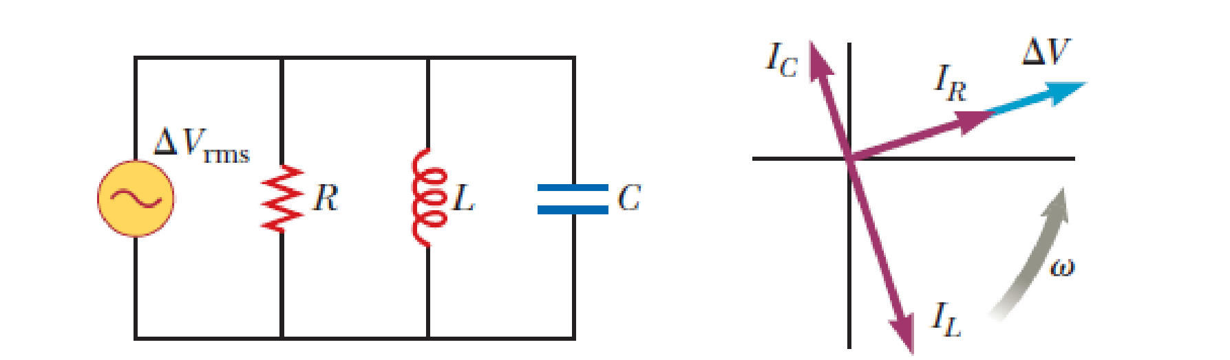
Figure P33.80a shows a parallel RLC circuit. The instantaneous voltages (and rms voltages) across each of the three circuit elements are the same, and each is in phase with the current in the resistor. The currents in C and L lead or lag the current in the resistor as shown in the current phasor diagram, Figure P33.80b. (a) Show that the rms current delivered by the source is
(b) Show that the phase angle ϕ between ΔVrms and Irms is given by
Want to see the full answer?
Check out a sample textbook solution
Chapter 33 Solutions
Physics for Scientists and Engineers with Modern, Revised Hybrid (with Enhanced WebAssign Printed Access Card for Physics, Multi-Term Courses)


- In a purely inductive AC circuit as shown in Figure P21.15, Vmax = 100. V. (a) The maximum current is 7.50 A at 50.0 Hz. Calculate the inductance L. (b) At what angular frequency is the maximum current 2.50A? Figure p21.15arrow_forwardAn inductor and a resistor are connected in series across an AC generator, as shown in Figure CQ21.16. Immediately after the switch is closed, which of the following statements is true? (a) The current is V/R. (b) The voltage across the inductor is zero. (c) The current in the circuit is zero. (d) The voltage across the resistor is V. (e) The voltage across the inductor is half its maximum value. Figure CQ21.16arrow_forwardIn an oscillating RLC circuit, R = 7.0 L. = 10 mH. And C = 3.0 F. Initially, the capacitor has a charge of 8.0 C and the current is zero. Calculate the charge on the capacitor (a) five cycles later and (b) 50 cycles later.arrow_forward
- P33.80a shows a parallel RLC circuit. The instantaneous voltages (and rms voltages) across each of the three circuit elements are the same, and each is in phase with the current in the resistor. The currents in C and L lead or lag the current in the resistor as shown in the current phasor diagram, Figure P33.80b. (a) Show that the rms current delivered by the source is Irms=Vrms[1R2+(C1L)2]12 (b) Show that the phase angle between Vrms and Irms is given by tan=R(1Xc1XL)arrow_forwardAn inductor and a resistor are connected in series across an AC generator, as shown in Figure CQ21.16. Immediately after the switch is closed, which of the following statements is true? (a) The current is V/R. (b) The voltage across the inductor is zero. (c) The current in the circuit is zero. (d) The voltage across the resistor is V. (e) The voltage across the inductor is half its maximum value. Figure CQ21.16arrow_forwardIn the AC circuit shown in Figure P32.3, R = 70.0 and the output voltage of the AC source is Vmax sin t. (a) If VR = 0.250 Vmax for the first time at t = 0.0100 s, what is the angular frequency of the source? (b) What is the next value of t for which VR = 0.250 Vmax? Figure P32.6 Problem 3 and 5.arrow_forward
- A series RLC circuit has resistance R = 50.0 and inductance L. = 0.500 H. (a) Find the circuits capacitance C if the voltage source operates at a frequency of f = 60.0 Hz and the impedance is Z = R = 50.0 . (b) What is the phase angle between the current and the voltage?arrow_forwardIn the transformer shown in Figure P33.51, the load resistance RL is 50.0 . The turns ratio N1/N2 is 2.50, anti the rms source voltage is Vs = 80.0 V. If a voltmeter across the load resistance measures an rms voltage of 25.0 V, what is the source resistance Rs?arrow_forwardAn AC source with Vmax = 150 V and f = 50.0 Hz is connected between points a and d in Figure P32.16. Calculate the maximum voltages between (a) points a and b, (b) points b and c, (c) points c and d, and (d) points b and d. Figure P32.16 Problems 16 and 51.arrow_forward
 Physics for Scientists and Engineers, Technology ...PhysicsISBN:9781305116399Author:Raymond A. Serway, John W. JewettPublisher:Cengage Learning
 Physics for Scientists and Engineers: Foundations...PhysicsISBN:9781133939146Author:Katz, Debora M.Publisher:Cengage Learning
 College PhysicsPhysicsISBN:9781285737027Author:Raymond A. Serway, Chris VuillePublisher:Cengage Learning
 College PhysicsPhysicsISBN:9781305952300Author:Raymond A. Serway, Chris VuillePublisher:Cengage Learning
 Physics for Scientists and EngineersPhysicsISBN:9781337553278Author:Raymond A. Serway, John W. JewettPublisher:Cengage Learning