VECTOR MECH. ENG. STATICS W/CONNECT >BI
12th Edition
ISBN: 9781260585612
Author: BEER
Publisher: MCG
bartleby

Videos

Textbook Question
Book Icon
Chapter 3.4, Problem 3.104P

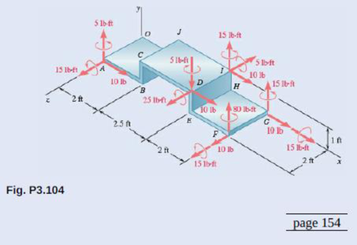
Five separate force-couple systems act at the corners of a piece of sheet metal that has been bent into the shape shown. Determine which of these systems is equivalent to a force F = (10 lb)i and a couple of moment M = (15 lb·ft)j + (15 lb·ft)k located at the origin.

Chapter 3.4, Problem 3.104P, Five separate force-couple systems act at the corners of a piece of sheet metal that has been bent

Expert Solution & Answer
Check Mark
To determine

Identify the system having force equivalent F=(10lb)i and moment equivalent M=(15lbft)j+((15lbft))k at origin.

Answer to Problem 3.104P

System at corner D is the equivalent force-couple system.

Explanation of Solution

Take counterclockwise torques as positive quantities and clockwise torques as negative quantities.

Refer Figure P3.104.

There are five systems at corners A,D,I,F, and Among these, system at corner F cannot be equivalent. This is because that it does not have force in x-direction. All other systems have force F=(10lb)i. Now, to identify the equivalent system, move all other systems to origin O. This will noT change the forces.

Write the expression to calculate the force part of force couple system.

R=F

Here, R is the vector sum of all forces acting on the beam and F denotes any individual force.

Let check the couple part of force-couple system.

Write the expression to calculate the couple part of force couple system.

MR=(r×F)

Here, MR is the resultant moment and r is the length from axis of rotation to the point of application of force.

In the given system, at points A,D,G and I, moments in two directions are directly given. So the expression to find (r×F) is as follows.

(r×F)=M1+M2+(r×F)

Here, M1andM2 are the given couple moments

Rewrite the equation for MR by substituting the above expression for (r×F).

MR=M1+M2+(r×F) (I)

Write the determinant form to calculate r×F.

r×F=|ijkrirjrkFiFjFk| (II)

Here, ri is the component of r in x-direction, rj is the component of r in y-direction, rk is the is the component of r in z-direction, Fi is the component of F in x-direction, Fj is the component of F in y-direction, and Fk is the component of F in z-direction.

Conclusion:

Substitute (5lbft)j for M1, (15lbft)k for M2, (2ft)k for r  and (10lb)i for F in equation  (I) to find  moment resultant of system at corner A about point O (MA) .

MA=(5lbft)j+(15lbft)k+((2ft)k×(10lb)i) (III)

Solve (2ft)k×(10lb)i using equation (II).

(2ft)k×(10lb)i=|ijk002ft10lb00|=(0lbft)i(0lbft20lbft)j+(0lbf)k=(20lbft)j

Calculate MA by substituting (2ft)k×(10lb)i for (20lbft)j in equation (III).

MA=(5lbft)j+(15lbft)k+(20lbft)j=(25lbft)j+(15lbft)k

Substitute  (5lbft)j for M1, (25lbft)k for M2, [(4.5ft)i+(1ft)j+(2ft)k](2ft)k for r  and (10lb)i for F in equation  (I) to find moment resultant of system at corner D about point O (MD).

MD=(5lbft)j+(25lbft)k+[(4.5ft)i+(1ft)j+(2ft)k]×(10lb)i(IV)

Solve [(4.5ft)i+(1ft)j+(2ft)k]×(10lb)i using equation (II).

[(4.5ft)i+(1ft)j+(2ft)k]×(10lb)i=|ijk4.5ft1ft2ft10lb00|=(0lbf)i(0lbft20lbft)j+(0lbft10lbft)k=(20lbft)j(10lbft)k

Calculate MD by substituting (20lbft)j(10lbft)k(2ft)k×(10lb)i for [(4.5ft)i+(1ft)j+(2ft)k]×(10lb)i(20lbft)j in equation (IV).

MD=(5lbft)j+(25lbft)k+(20lbft)j(10lbft)k=(15lbft)j+(15lbft)k

Substitute  (15lbft)i for M1, (15lbft)j for M2, [(0ft)i+(0ft)j+(0ft)k] for r  and (10lb)i for F in equation  (I) to find moment resultant of system at corner G about point O (MG).

MG=(15lbft)i+(15lbft)j+[(0ft)i+(0ft)j+(0ft)k]×(10lb)i=(15lbft)i+(15lbft)j+(0ft)i+(0ft)j+(0ft)k=(15lbft)i+(15lbft)j

Substitute  (15lbft)j for M1, (5lbft)k for M2, [(4.5ft)i+(1ft)j] for r  and (10lb)j for F in equation  (I) to find moment resultant of system at corner I about point O (MI).

MD=(15lbft)j+(5lbft)k+([(4.5ft)i+(1ft)j]×(10lb)j)(V)

Solve [(4.5ft)i+(1ft)j]×(10lb)j using equation (III).

[(4.5ft)i+(1ft)j]×(10lb)j=|ijk(4.5ft)(1ft)(0ft)(10lb)00|=(0lbf)i(0lbft)j+(0lbft10lbft)k(10lbft)k

Calculate MD by substituting (10lbft)k for [(4.5ft)i+(1ft)j]×(10lb)j(20lbft)j in equation (V).

MI=(15lbft)j(5lbft)k+(10lbft)k=(15lbft)j(15lbft)k

From the above calculations, it is found that system at corner D has force equivalent F=(10lb)i and moment equivalent M=(15lbft)j+((15lbft))k at origin.

Therefore, System at corner D is the equivalent force-couple system.

Want to see more full solutions like this?

Subscribe now to access step-by-step solutions to millions of textbook problems written by subject matter experts!
Students have asked these similar questions
A robotic arm working according to the coordinate position. The force F1 (N) applied to the workpiece is held at the end of the arm of the robot.- Express force F1 as unit vectors i and j corresponding to x and y axes.- Calculate the value of the moment due to the force F1 acting about the center of rotation (O) of the robot arm, knowing the distance from the point of application of the force to the center through O is L (mm)
The force-couple system shown acts on a trapezoidal plate.a. Determine the value of M1 if the system shown is equivalent to a single force acting at point C.b. The system shown is equivalent to a force-couple system consisting of R and M2 = 3000 kip-inclockwise. If M1 in this case is 120 kip-in counterclockwise, determine the point of action of theresultant force R along line CD.
The force-couple system shown acts on a trapezoidal plate. a. Determine the value of M1 if the system shown is equivalent to a single force acting at point C. b. The system shown is equivalent to a force-couple system consisting of R and M2 = 3000 kip-in clockwise. If M1 in this case is 120 kip-in counterclockwise, determine the point of action of the resultant force R along line CD.

Chapter 3 Solutions

VECTOR MECH. ENG. STATICS W/CONNECT >BI

Ch. 3.1 - 3.11 and 3.12The tailgate of a car is supported by...Ch. 3.1 - 3.11 and 3.12The tailgate of a car is supported by...Ch. 3.1 - 3.13 and 3.14It is known that the connecting rod...Ch. 3.1 - 3.13 and 3.14It is known that the connecting rod...Ch. 3.1 - Form the vector product P1 P2 and use the result...Ch. 3.1 - The vectors P and Q are two adjacent sides of a...Ch. 3.1 - Prob. 3.17PCh. 3.1 - Prob. 3.18PCh. 3.1 - Prob. 3.19PCh. 3.1 - Prob. 3.20PCh. 3.1 - Before the trunk of a large tree is felled, cables...Ch. 3.1 - The 12-ft boom AB has a fixed end A. A steel cable...Ch. 3.1 - A 200-N force is applied as shown to the bracket...Ch. 3.1 - A force P of magnitude 200 N acts along the...Ch. 3.1 - A 6-ft-long fishing rod AB is securely anchored in...Ch. 3.1 - A precast concrete wall section is temporarily...Ch. 3.1 - In Prob. 3.22, determine the perpendicular...Ch. 3.1 - In Prob. 3.23, determine the perpendicular...Ch. 3.1 - In Prob. 3.24, determine the perpendicular...Ch. 3.1 - In Prob. 3.25, determine the perpendicular...Ch. 3.1 - In Prob. 3.25, determine the perpendicular...Ch. 3.1 - In Prob. 3.26, determine the perpendicular...Ch. 3.1 - In Prob. 3.26, determine the perpendicular...Ch. 3.1 - Determine the value of a that minimizes the...Ch. 3.2 - Given the vectors P = 2i + j + 2k, Q = 3i + 4j ...Ch. 3.2 - Form the scalar product B C and use the result...Ch. 3.2 - Three cables are attached to the top of the tower...Ch. 3.2 - Prob. 3.38PCh. 3.2 - Knowing that the tension in cable AC is 280 lb,...Ch. 3.2 - Knowing that the tension in cable AD is 180 lb,...Ch. 3.2 - Ropes AB and BC are two of the ropes used to...Ch. 3.2 - Ropes AB and BC are two of the ropes used to...Ch. 3.2 - The 20-in. tube AB can slide along a horizontal...Ch. 3.2 - Solve Prob. 3.43 for the position corresponding to...Ch. 3.2 - Determine the volume of the parallelepiped of Fig....Ch. 3.2 - Prob. 3.46PCh. 3.2 - A crane is oriented so that the end of the 25-m...Ch. 3.2 - 3.48The 25-m crane boom AO lies in the yz plane....Ch. 3.2 - To loosen a frozen valve, a force F with a...Ch. 3.2 - 3.50When a force F is applied to the handle of the...Ch. 3.2 - The 0.61 1.00-m lid ABCD of a storage bin is...Ch. 3.2 - Prob. 3.52PCh. 3.2 - A farmer uses cables and winch pullers B and E to...Ch. 3.2 - Solve Prob. 3.53 when the tension in cable AB is...Ch. 3.2 - A force P of magnitude 520 lb acts on the frame...Ch. 3.2 - 3.56A force P acts on the frame shown at point E....Ch. 3.2 - The frame ACD is hinged at A and D and is...Ch. 3.2 - In Prob. 3.57, determine the moment about the...Ch. 3.2 - The triangular plate ABC is supported by...Ch. 3.2 - 3.60The triangular plate ABC is supported by...Ch. 3.2 - Prob. 3.61PCh. 3.2 - Prob. 3.62PCh. 3.2 - Two forces F1 and F2 in space have the same...Ch. 3.2 - Prob. 3.64PCh. 3.2 - Prob. 3.65PCh. 3.2 - In Prob. 3.57, determine the perpendicular...Ch. 3.2 - In Prob. 3.58, determine the perpendicular...Ch. 3.2 - In Prob. 3.59, determine the perpendicular...Ch. 3.2 - In Prob. 3.60, determine the perpendicular...Ch. 3.3 - Two 80-N forces are applied as shown to the...Ch. 3.3 - Two parallel 60-N forces are applied as shown to...Ch. 3.3 - A multiple-drilling machine is used to drill...Ch. 3.3 - Four pegs of the same diameter are attached to a...Ch. 3.3 - A piece of plywood in which several holes are...Ch. 3.3 - The shafts of an angle drive are acted upon by the...Ch. 3.3 - Prob. 3.76PCh. 3.3 - 3.77If P = 20 lb in the figure, replace the three...Ch. 3.3 - The two couples shown are to be replaced with a...Ch. 3.3 - Solve part a of Prob. 3.78, assuming that two 15-N...Ch. 3.3 - Shafts A and B connect the gear box to the wheel...Ch. 3.3 - A 500-N force is applied to a bent plate as shown....Ch. 3.3 - A crane column supports a 16-kip load as shown....Ch. 3.3 - A dirigible is tethered by a cable attached to its...Ch. 3.3 - A 30-lb vertical force P is applied at A to the...Ch. 3.3 - A worker tries to move a rock by applying a 360-N...Ch. 3.3 - A worker tries to move a rock by applying a 360-N...Ch. 3.3 - The shearing forces exerted on the cross section...Ch. 3.3 - Knowing that = 60, replace the force and couple...Ch. 3.3 - Three control rods attached to a lever ABC exert...Ch. 3.3 - A rectangular plate is acted upon by the force and...Ch. 3.3 - While tapping a hole, a machinist applies the...Ch. 3.3 - A hexagonal plate is acted upon by the force P and...Ch. 3.3 - Replace the 250-kN force P with an equivalent...Ch. 3.3 - A 2.6-kip force is applied at point D of the...Ch. 3.3 - Replace the 150-N force with an equivalent...Ch. 3.3 - To keep a door closed, a wooden stick is wedged...Ch. 3.3 - A 46-lb force F and a 2120-lbin. couple M are...Ch. 3.3 - A 110-N force acting in a vertical plane parallel...Ch. 3.3 - The 12-ft boom AB has a fixed end A, and the...Ch. 3.3 - The jib crane shown is oriented so that its boom...Ch. 3.4 - 3.101A 4-m-long beam is subjected to a variety of...Ch. 3.4 - Prob. 3.102PCh. 3.4 - Determine the single equivalent force and the...Ch. 3.4 - Five separate force-couple systems act at the...Ch. 3.4 - The weights of two children sitting at ends A and...Ch. 3.4 - Three stage lights are mounted on a pipe as shown....Ch. 3.4 - A beam supports three loads of given magnitude and...Ch. 3.4 - A 6 12-in. plate is subjected to four loads as...Ch. 3.4 - Gear C is rigidly attached to arm AB. If the...Ch. 3.4 - To test the strength of a 625 500-mm suitcase,...Ch. 3.4 - Two cables exert forces of 90 kN each on a truss...Ch. 3.4 - Pulleys A and B are mounted on bracket CDEF. The...Ch. 3.4 - The roof of a building frame is subjected to the...Ch. 3.4 - A couple of magnitude M = 80 lbin. and the three...Ch. 3.4 - A couple M and the three forces shown are applied...Ch. 3.4 - A machine component is subjected to the forces and...Ch. 3.4 - Solve Prob. 3.116, assuming that P = 60 N.Ch. 3.4 - As follower AB rolls along the surface of member...Ch. 3.4 - A machine component is subjected to the forces...Ch. 3.4 - Two 150-mm-diameter pulleys are mounted on line...Ch. 3.4 - As an adjustable brace BC is used to bring a wall...Ch. 3.4 - In order to unscrew the tapped faucet A, a plumber...Ch. 3.4 - Assuming = 60 in Prob. 3.122, replace the two...Ch. 3.4 - Four forces are applied to the machine component...Ch. 3.4 - A blade held in a brace is used to tighten a screw...Ch. 3.4 - A mechanic uses a crowfoot wrench to loosen a bolt...Ch. 3.4 - Prob. 3.127PCh. 3.4 - Prob. 3.128PCh. 3.4 - Four signs are mounted on a frame spanning a...Ch. 3.4 - Prob. 3.130PCh. 3.4 - A concrete foundation mat of 5-m radius supports...Ch. 3.4 - Determine the magnitude and the point of...Ch. 3.4 - Prob. 3.133PCh. 3.4 - A piece of sheet metal is bent into the shape...Ch. 3.4 - Prob. 3.135PCh. 3.4 - Prob. 3.136PCh. 3.4 - Two bolts at A and B are tightened by applying the...Ch. 3.4 - Two bolts at A and B are tightened by applying the...Ch. 3.4 - Prob. 3.139PCh. 3.4 - A flagpole is guyed by three cables. If the...Ch. 3.4 - 3.141 and 3.142Determine whether the...Ch. 3.4 - 3.141 and 3.142Determine whether the...Ch. 3.4 - Replace the wrench shown with an equivalent system...Ch. 3.4 - Show that, in general, a wrench can be replaced...Ch. 3.4 - Show that a wrench can be replaced with two...Ch. 3.4 - Show that a wrench can be replaced with two...Ch. 3 - A 300-N force P is applied at point A of the bell...Ch. 3 - A winch puller AB is used to straighten a fence...Ch. 3 - A small boat hangs from two davits, one of which...Ch. 3 - Prob. 3.150RPCh. 3 - A single force P acts at C in a direction...Ch. 3 - The 23-in. vertical rod CD is welded to the...Ch. 3 - In a manufacturing operation, three holes are...Ch. 3 - A 260-lb force is applied at A to the rolled-steel...Ch. 3 - Prob. 3.155RPCh. 3 - A 77-N force F1 and a 31-Nm couple M1 are applied...Ch. 3 - Three horizontal forces are applied as shown to a...Ch. 3 - While using a pencil sharpener, a student applies...
Knowledge Booster
Background pattern image
Mechanical Engineering
Learn more about
Need a deep-dive on the concept behind this application? Look no further. Learn more about this topic, mechanical-engineering and related others by exploring similar questions and additional content below.
Similar questions
SEE MORE QUESTIONS
Recommended textbooks for you
Text book image
International Edition---engineering Mechanics: St...
Mechanical Engineering
ISBN:9781305501607
Author:Andrew Pytel And Jaan Kiusalaas
Publisher:CENGAGE L
How to balance a see saw using moments example problem; Author: Engineer4Free;https://www.youtube.com/watch?v=d7tX37j-iHU;License: Standard Youtube License