Concept explainers
Videos
Two 150-mm-diameter pulleys are mounted on line shaft AD. The belts at B and C lie in vertical planes parallel to the yz plane. Replace the belt forces shown with an equivalent force-couple system at A.
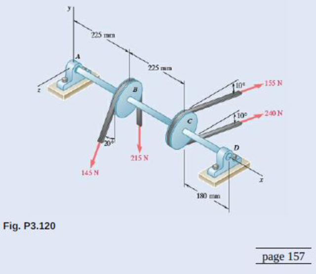
Replace the given system with its equivalent force-couple system at POINT A.
Answer to Problem 3.120P
The equivalent force is
Explanation of Solution
Refer Fig P3.120. Its vector diagrams showing equivalent force-couple is given below.
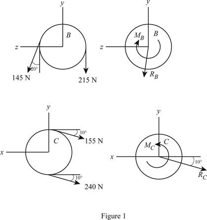
Write the formula to calculate the resultant force pulley B.
Here,
Write the formula to calculate the net moment of couple on pulley B.
Here,
Write the formula to calculate the resultant force pulley C.
Here,
Write the formula to calculate the net moment of couple on pulley B.
Here,
Write the expression to calculate the net force on pulley.
Here,
Write the expression to calculate the resultant moment of couple about point A.
Here,
Write the determinant form to calculate
Here,
Conclusion:
Substitute
Substitute
Substitute
Substitute
Substitute
Substitute
Calculate
Calculate
Rewrite equation (IIX) by substituting equations (IX) and (X).
Therefore, the equivalent force is
Want to see more full solutions like this?
Chapter 3 Solutions
Loose Leaf for Vector Mechanics for Engineers: Statics


- The four forces shown act on the rollers of an in-line skate. Determine the equivalent force-couple system, with the force acting at O (the ankle joint of the skater).arrow_forwardDetermine the wrench that is equivalent to the force-couple system shown and find the coordinates of the point where the axis of the wrench crosses the xz-plane.arrow_forwardThe figure shows one-half of a universal coupling known as the Hooke's joint. The coupling is acted on by the three couples shown: (a) the input couple consisting of forces of magnitude P, (b) the output couple C0, and (c) the couple formed by bearing reactions of magnitude R. If the resultant of these couples is zero, compute R and C0 for P=750lb.arrow_forward
- A couple of magnitude 3601b ft is applied about portion AB of the drive shaft (the drive shaft is connected by universal joints at points B and C). Compute the moment of the applied couple about the portion CD when the drive shaft is in the position shown.arrow_forwardThe steering column of the rack-and-pinion steering mechanism lies in the xz-plane. The tube AB of the steering gear is attached to the automobile chassis at A and B. When the steering wheel is turned, the assembly is subjected to the four couples shown: the 3-N m couple applied by the driver to the steering wheel, two 1.8-N m couples (one at each wheel), and the couple formed by the two forces of magnitude F acting at A and B. If the resultant couple acting on the steering mechanism is zero, determine F and the angle (the magnitude and direction of the bearing reactions).arrow_forwardThe couple acts on the handles of a steering mechanism. In the position shown, the moment applied by the couple about the z-axis is zero. Determine the distance b. Use F=150i90j+60kkN.arrow_forward
- Three cables are attached to a bracket as shown. Replace the forces exerted by the cables with an equivalent force-couple system at Aarrow_forwardIn order to design the foundation for the utility pole shown to the right, replace the system of three applied forces with an equivalent force- couple system applied at point A.arrow_forwardA 2.6-kip force is applied at point D of the cast-iron post shown. Replace that force with an equivalent force-couple system at the center A of the base section.arrow_forward
- A 46-lb force F and a 2120-lb·in. couple M are applied to corner A of the block shown. Replace the given force-couple system with an equivalent force-couple system at corner H.arrow_forwardThe pulley and gear are subjected to the loads shown. For these forces, determine the equivalent force-couple system at point ?.arrow_forwardThe tension in the cable attached to the end C of an adjustable boom ABC is 560 lb. Replace the force exerted by the cable at C with an equivalent force-couple system (a) at A, (b) at B.arrow_forward
 International Edition---engineering Mechanics: St...Mechanical EngineeringISBN:9781305501607Author:Andrew Pytel And Jaan KiusalaasPublisher:CENGAGE L