
Mechanics of Materials, Student Value Edition (10th Edition)
10th Edition
ISBN: 9780134321189
Author: Russell C. Hibbeler
Publisher: PEARSON
expand_more
expand_more
format_list_bulleted
Videos
Textbook Question
Chapter 3.4, Problem 3.12P
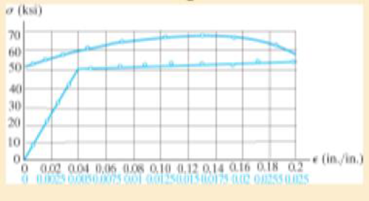
The stress-strain diagram for an aluminum alloy specimen having an original diameter of 0.5 in. and a gage length of 2 in. is given in the figure. Determine approximately the modulus of resilience and the modulus of toughness for the material.
Expert Solution & Answer
Want to see the full answer?
Check out a sample textbook solution
Students have asked these similar questions
The stress-strain diagram for an aluminum alloy specimen having an original diameter of 0.5 in. and a gauge length of 2 in. is given in the figure. If the specimen is loaded until it is stressed to 60 ksi, determine the approximate amount of elastic recovery and the increase in the gage length after it is unloaded.
The stress–strain diagram for an aluminum alloy specimen having an original diameter of 0.5 in. and a gauge length of 2 in. is given in the figure. Determine approximately the modulus of resilience and the modulus of toughness for the material.
The stress–strain diagram for a steel alloy having an original diameter of 0.5 in. and a gage length of 2 in. is given in the figure. If the specimen is loaded until it is stressed to 70 ksi, determine the approximate amount of elasticrecovery and the increase in the gage length after it is unloaded.
Chapter 3 Solutions
Mechanics of Materials, Student Value Edition (10th Edition)
Ch. 3.4 - Define a homogeneous material.Ch. 3.4 - Indicate the points on the stress-strain diagram...Ch. 3.4 - Define the modulus of elasticity E.Ch. 3.4 - At room temperature, mild steel is a ductile...Ch. 3.4 - Engineering stress and strain are calculated using...Ch. 3.4 - As the temperature increases the modulus of...Ch. 3.4 - A 100-mm-long rod has a diameter of 15 mm. If an...Ch. 3.4 - A bar has a length of 8 in. and cross-sectional...Ch. 3.4 - A 10-mm-diameter rod has a modulus of elasticity...Ch. 3.4 - The material for the 50-mm-long specimen has the...
Ch. 3.4 - The material for the 50-mm-long specimen has the...Ch. 3.4 - If the elongation of wire BC is 0.2 mm after the...Ch. 3.4 - A tension test was performed on a steel specimen...Ch. 3.4 - Data taken from a stress-strain test for a ceramic...Ch. 3.4 - Data taken from a stress-strain test for a ceramic...Ch. 3.4 - The stress-strain diagram for a steel alloy having...Ch. 3.4 - The stress-strain diagram for a steel alloy having...Ch. 3.4 - The stress-strain diagram for a steel alloy having...Ch. 3.4 - The rigid beam is supported by a pin at C and an...Ch. 3.4 - The rigid beam is supported by a pin at C and an...Ch. 3.4 - Acetal plastic has a stress-strain diagram as...Ch. 3.4 - The stress-strain diagram for an aluminum alloy...Ch. 3.4 - The stress-strain diagram for an aluminum alloy...Ch. 3.4 - The stress-strain diagram for an aluminum alloy...Ch. 3.4 - A bar having a length of 5 in. and cross-sectional...Ch. 3.4 - The rigid pipe is supported by a pin at A and an...Ch. 3.4 - The rigid pipe is supported by a pin at A and an...Ch. 3.4 - Direct tension indicators are sometimes used...Ch. 3.4 - The rigid beam is supported by a pin at C and an...Ch. 3.4 - The rigid beam is supported by a pin at C and an...Ch. 3.4 - The stress-strain diagram for a bone is shown, and...Ch. 3.4 - The stress-strain diagram for a bone is shown and...Ch. 3.4 - The two bars are made of a material that has the...Ch. 3.4 - The two bars are made of a material that has the...Ch. 3.4 - The pole is supported by a pin at C and an A-36...Ch. 3.4 - The bar DA is rigid and is originally held in the...Ch. 3.7 - A 100-mm-long rod has a diameter of 15 mm. If an...Ch. 3.7 - A solid circular rod that is 600 mm long and 20 mm...Ch. 3.7 - A 20-mm-wide block is firmly bonded to rigid...Ch. 3.7 - A 20-mm-wide block is bonded to rigid plates at...Ch. 3.7 - The acrylic plastic rod is 200 mm long and 15 mm...Ch. 3.7 - The plug has a diameter of 30 mm and fits within a...Ch. 3.7 - The elastic portion of the stress-strain diagram...Ch. 3.7 - The elastic portion of the stress-strain diagram...Ch. 3.7 - The brake pads for a bicycle tire are made of...Ch. 3.7 - The lap joint is connected together using a 1.25...Ch. 3.7 - The lap joint is connected together using a 1.25...Ch. 3.7 - The rubber block is subjected to an elongation of...Ch. 3.7 - The shear stress-strain diagram for an alloy is...Ch. 3.7 - A shear spring is made from two blocks of rubber,...Ch. 3 - The elastic portion of the tension stress-strain...Ch. 3 - The elastic portion of the tension stress-strain...Ch. 3 - The rigid beam rests in the horizontal position on...Ch. 3 - The wires each have a diameter of 12 in., length...Ch. 3 - The wires each have a diameter of 12 in., length...Ch. 3 - diameter steel bolts. If the clamping force in...Ch. 3 - The stress-strain diagram for polyethylene, which...Ch. 3 - The pipe with two rigid caps attached to its ends...Ch. 3 - The 8-mm-diameter bolt is made of an aluminum...Ch. 3 - An acetal polymer block is fixed to the rigid...
Knowledge Booster


Learn more about
Need a deep-dive on the concept behind this application? Look no further. Learn more about this topic, mechanical-engineering and related others by exploring similar questions and additional content below.Similar questions
- An element of material in plain strain has the following strains: x = 0.001 and y = 0.0015. (a) Determine the strains for an element oriented at an angle = 250. (b) Find the principal strains of the element. Confirm the solution using Mohr’s circle for plane strain.arrow_forwardA solid spherical ball of magnesium alloy (E = 6.5 × l0-6 psi, v = 0.35) is lowered into the ocean to a depth of 8000 ft. The diameter of the ball is 9.0 in. (a) Determine the decrease ?d in diameter, the decrease, ?V in volume, and the strain energy U of the ball. (b) At what depth will the volume change be equal to 0.0324% of the original volume?arrow_forwardAn element of material in plain strain is subjected to shear strain xy = 0.0003. (a) Determine the strains for an element oriented at an angle = 30°. (b) Determine the principal strains of the clement. Confirm the solution using Mohr’s circle for plane strain.arrow_forward
- - 7.2-26 The strains on the surface of an experiment al device made of pure aluminum (E = 70 GPa. v = 0.33) and tested in a space shuttle were measured by means of strain gages. The gages were oriented as shown in the figure. and the measured strains were = 1100 X 106, h = 1496 X 10.6, and = 39.44 X l0_. What is the stress o in the x direction?arrow_forwardA spherical balloon with an outer diameter of 500 mm and thickness 0.3 mm is filled with a gas. Calculate maximum permissible pressure in the balloon if the allowable normal strain at the outer surface of the balloon is O.h Assume E = 4 MPa and v = 0,45.arrow_forwardThe state of stress on an element of material is shown in the figure. Calculate the unit volume change of the element if the stresses x and y. are -20 ksi and 10 ksi, respectively. Assume E = 10,600 ksi and v = 0.33.arrow_forward
- Solve the preceding problem if the plate is made of aluminum with E = 72 GPa and Poisson’s ratio v = 0.33. The plate is loaded in biaxial stress with normal stress sx= 79 MPa, angle Ø = 18°, and the strain measured by the gage is e = 925 × 10-6.arrow_forwardA prismatic bar in tension has a length L = 2.0 m and cross-sectional area A =249 mn2. The material of the bar has the stress-strain curve shown in the figure. Determi ne t he elongation 5 of the bar for each of the following axial loads: P = 10 kN, 20 kN, 30 kN, 40 kN. and 45 kN. From these results, plot a diagram of load P versus elongation 5 (load-displacement diagram).arrow_forwardThe rails of a railroad track are welded together at their ends (to form continuous rails and thus eliminate the clacking sound of the wheels) when the temperature is 60°F. What compressive stress ?? =6.5×10⁻⁶ /? is produced in the rails when they are heated by the sun to 120"F if the coefficient of thermal expansion a = the modulus of elasticity E = 30 × 106 psi?arrow_forward
- 1 A rectangular steel plate with thickness t = 5/8 in. is subjected to uniform normal stresses a and ., as shown in the figure. Strain gages A and B. oriented in the x and v directions. respectively, arc attached to the plate. The gage readings give normal strains = 0.00065 (elongation) and £. = 0.00040 (elongation). Knowing that E = 30 X 106 psi and v = 0.3, determine the stresses c7 and a, and the change .11 in the thickness of the plate.arrow_forwardA strain rosette (see figure) mounted on the surface of an automobile frame gives the following readings: gage A,310 × 10-6:gage B,180 × l0-6; and gage C. -160 × 10-6. Determine the principal strains and maximum shear strains, and show them on sketches of properly oriented elements.arrow_forwardSolve the preceding problem if the cross- sectional dimensions are b = 1.5 in. and h = 5.0 in., the gage angle is ß = 750, the measured strains are = 209 × 10-6 and B = -110 × 10, and the material is a magnesium alloy with modulus E = 6.0 X 10⁶ psi and Poisson’s ratio v = 0.35.arrow_forward
arrow_back_ios
SEE MORE QUESTIONS
arrow_forward_ios
Recommended textbooks for you
 Mechanics of Materials (MindTap Course List)Mechanical EngineeringISBN:9781337093347Author:Barry J. Goodno, James M. GerePublisher:Cengage Learning
Mechanics of Materials (MindTap Course List)
Mechanical Engineering
ISBN:9781337093347
Author:Barry J. Goodno, James M. Gere
Publisher:Cengage Learning
Lec21, Part 5, Strain transformation; Author: Mechanics of Materials (Libre);https://www.youtube.com/watch?v=sgJvz5j_ubM;License: Standard Youtube License