
Mechanics of Materials
10th Edition
ISBN: 9780134321158
Author: HIBBELER
Publisher: PEARSON
expand_more
expand_more
format_list_bulleted
Concept explainers
Videos
Textbook Question
Chapter 3.4, Problem 3.3P
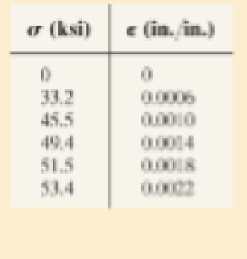
Data taken from a stress-strain test for a ceramic are given in the table. The curve is linear between the origin and the first point. Plot the diagram, and determine approximately the modulus of toughness. The fracture stress is σf = 53.4 ksi.
Expert Solution & Answer
Want to see the full answer?
Check out a sample textbook solution
Students have asked these similar questions
Data taken from a stress-strain test for a ceramic are given in the table. The curve is linear between the origin and the first point. Plot the diagram, and determine the modulus of elasticity and the modulus of resilience.
20) If the area under the stress and strain curve is more then it is concluded that the material has high stress
Select one:
True
False
The strain value of the structure in the same direction as a result of the pull applied in the X axis from the bottom was measured as 0.26 mm / mm. Under the same loading condition: a) Calculate the strain on the Z axis of the structure. b) In this case, what is the strain type of the structure in the Z axis?
Chapter 3 Solutions
Mechanics of Materials
Ch. 3.4 - Define a homogeneous material.Ch. 3.4 - Indicate the points on the stress-strain diagram...Ch. 3.4 - Define the modulus of elasticity E.Ch. 3.4 - At room temperature, mild steel is a ductile...Ch. 3.4 - Engineering stress and strain are calculated using...Ch. 3.4 - As the temperature increases the modulus of...Ch. 3.4 - A 100-mm-long rod has a diameter of 15 mm. If an...Ch. 3.4 - A bar has a length of 8 in. and cross-sectional...Ch. 3.4 - A 10-mm-diameter rod has a modulus of elasticity...Ch. 3.4 - The material for the 50-mm-long specimen has the...
Ch. 3.4 - The material for the 50-mm-long specimen has the...Ch. 3.4 - If the elongation of wire BC is 0.2 mm after the...Ch. 3.4 - A tension test was performed on a steel specimen...Ch. 3.4 - Data taken from a stress-strain test for a ceramic...Ch. 3.4 - Data taken from a stress-strain test for a ceramic...Ch. 3.4 - The stress-strain diagram for a steel alloy having...Ch. 3.4 - The stress-strain diagram for a steel alloy having...Ch. 3.4 - The stress-strain diagram for a steel alloy having...Ch. 3.4 - The rigid beam is supported by a pin at C and an...Ch. 3.4 - The rigid beam is supported by a pin at C and an...Ch. 3.4 - Acetal plastic has a stress-strain diagram as...Ch. 3.4 - The stress-strain diagram for an aluminum alloy...Ch. 3.4 - The stress-strain diagram for an aluminum alloy...Ch. 3.4 - The stress-strain diagram for an aluminum alloy...Ch. 3.4 - A bar having a length of 5 in. and cross-sectional...Ch. 3.4 - The rigid pipe is supported by a pin at A and an...Ch. 3.4 - The rigid pipe is supported by a pin at A and an...Ch. 3.4 - Direct tension indicators are sometimes used...Ch. 3.4 - The rigid beam is supported by a pin at C and an...Ch. 3.4 - The rigid beam is supported by a pin at C and an...Ch. 3.4 - The stress-strain diagram for a bone is shown, and...Ch. 3.4 - The stress-strain diagram for a bone is shown and...Ch. 3.4 - The two bars are made of a material that has the...Ch. 3.4 - The two bars are made of a material that has the...Ch. 3.4 - The pole is supported by a pin at C and an A-36...Ch. 3.4 - The bar DA is rigid and is originally held in the...Ch. 3.7 - A 100-mm-long rod has a diameter of 15 mm. If an...Ch. 3.7 - A solid circular rod that is 600 mm long and 20 mm...Ch. 3.7 - A 20-mm-wide block is firmly bonded to rigid...Ch. 3.7 - A 20-mm-wide block is bonded to rigid plates at...Ch. 3.7 - The acrylic plastic rod is 200 mm long and 15 mm...Ch. 3.7 - The plug has a diameter of 30 mm and fits within a...Ch. 3.7 - The elastic portion of the stress-strain diagram...Ch. 3.7 - The elastic portion of the stress-strain diagram...Ch. 3.7 - The brake pads for a bicycle tire are made of...Ch. 3.7 - The lap joint is connected together using a 1.25...Ch. 3.7 - The lap joint is connected together using a 1.25...Ch. 3.7 - The rubber block is subjected to an elongation of...Ch. 3.7 - The shear stress-strain diagram for an alloy is...Ch. 3.7 - A shear spring is made from two blocks of rubber,...Ch. 3 - The elastic portion of the tension stress-strain...Ch. 3 - The elastic portion of the tension stress-strain...Ch. 3 - The rigid beam rests in the horizontal position on...Ch. 3 - The wires each have a diameter of 12 in., length...Ch. 3 - The wires each have a diameter of 12 in., length...Ch. 3 - diameter steel bolts. If the clamping force in...Ch. 3 - The stress-strain diagram for polyethylene, which...Ch. 3 - The pipe with two rigid caps attached to its ends...Ch. 3 - The 8-mm-diameter bolt is made of an aluminum...Ch. 3 - An acetal polymer block is fixed to the rigid...
Knowledge Booster


Learn more about
Need a deep-dive on the concept behind this application? Look no further. Learn more about this topic, mechanical-engineering and related others by exploring similar questions and additional content below.Similar questions
- The stress–strain diagram for a steel alloy having an original diameter of 0.5 in. and a gage length of 2 in. is given in the figure. If the specimen is loaded until it is stressed to 70 ksi, determine the approximate amount of elasticrecovery and the increase in the gage length after it is unloaded.arrow_forwardThe stress–strain diagram for an aluminum alloy specimen having an original diameter of 0.5 in. and a gauge length of 2 in. is given in the figure. Determine approximately the modulus of resilience and the modulus of toughness for the material.arrow_forwardAs a result of the tension applied from the base in the X axis, the strain value of the structure in the same direction was measured as 0.26 mm / mm. Under the same loading condition: a) Calculate the strain of the structure in the Z axis. b) In this case, what is the type of strain on the Z axis?arrow_forward
- The stress-strain diagram for an aluminum alloy specimen having an original diameter of 0.5 in. and a gauge length of 2 in. is given in the figure. If the specimen is loaded until it is stressed to 60 ksi, determine the approximate amount of elastic recovery and the increase in the gage length after it is unloaded.arrow_forwardThe A-36 steel bar consists of two segments, one of a circular cross-section of radius r, and one of square cross-section. If the bar is subjected to the axial loading of P, determine the dimensions of the square segment so that the strain energy within the square segment is the same as in the circular segment.arrow_forwardThe specimen represents a filament-reinforced matrix system made from plastic (matrix) and glass (fiber). If there are n fibers, each having a cross-sectional area of Af and modulus of Ef, embedded in a matrix having a cross-sectional area of Am and modulus of Em, determine the stress in the matrix and in each fiber when the force P is applied on the specimenarrow_forward
- The modulus of elasticity for the steel cable is 25 (10)^6 psi. Determine the average stress in the cable under the applied load. Assume a linear stress strain curve.arrow_forwardThe bar has a cross-sectional area of 0.5 in2 and is made of a material that has a stress-strain diagram that can be approximated by the two line segments. Determine the elongation of the bar due to the applied loading.arrow_forwardA tension test was performed on a steel specimen having an original diameter of 12.5 mm and gauge length of 50 mm. The data is listed in the table. Plot the stress–strain diagram and determine approximately the modulus of elasticity, the yield stress, the ultimate stress, and the rupture stress. Use a scale of 25 mm = 140 MPa and 25 mm = 0.05 mm/mm. Redraw the elastic region, using the same stress scale but a strain scale of 25 mm = 0.001 mm/mm.arrow_forward
- The 60° strain rosette is mounted on the surface of the bracket. The following readings are obtained for each gage: Pa = -780(10-6), Pb = 400(10-6), and Pc = 500(10-6). Determine (a) the principal strains and (b) the maximumin-plane shear strain and associated average normal strain. In each case show the deformed element due to these strains.arrow_forwardThe piece of plastic is originally rectangular. Determine the average normal strain that occurs along the diagonals AC and DB. Determine the shear strain at corners A and B if the plastic distorts as shown by the dashed lines.arrow_forwardThe ply stress σα was calculated for AS1/3501-6 Graphite/Epoxy laminates [0/+-45]s under load with N1=10,000 N/m and N2=N6=0. When the strength of this material is as follows, determine the stability of the laminate according to the maximum stress theory.arrow_forward
arrow_back_ios
SEE MORE QUESTIONS
arrow_forward_ios
Recommended textbooks for you
 Mechanics of Materials (MindTap Course List)Mechanical EngineeringISBN:9781337093347Author:Barry J. Goodno, James M. GerePublisher:Cengage Learning
Mechanics of Materials (MindTap Course List)
Mechanical Engineering
ISBN:9781337093347
Author:Barry J. Goodno, James M. Gere
Publisher:Cengage Learning
Strain energy and strain energy density introduced; Author: Engineer4Free;https://www.youtube.com/watch?v=m14sqLGg4BQ;License: Standard youtube license