
STANDALONE CODE MECHANICS OF MATERIALS-M
11th Edition
ISBN: 9780137605200
Author: HIBBELER
Publisher: PEARSON
expand_more
expand_more
format_list_bulleted
Videos
Textbook Question
Chapter 3.4, Problem 4P
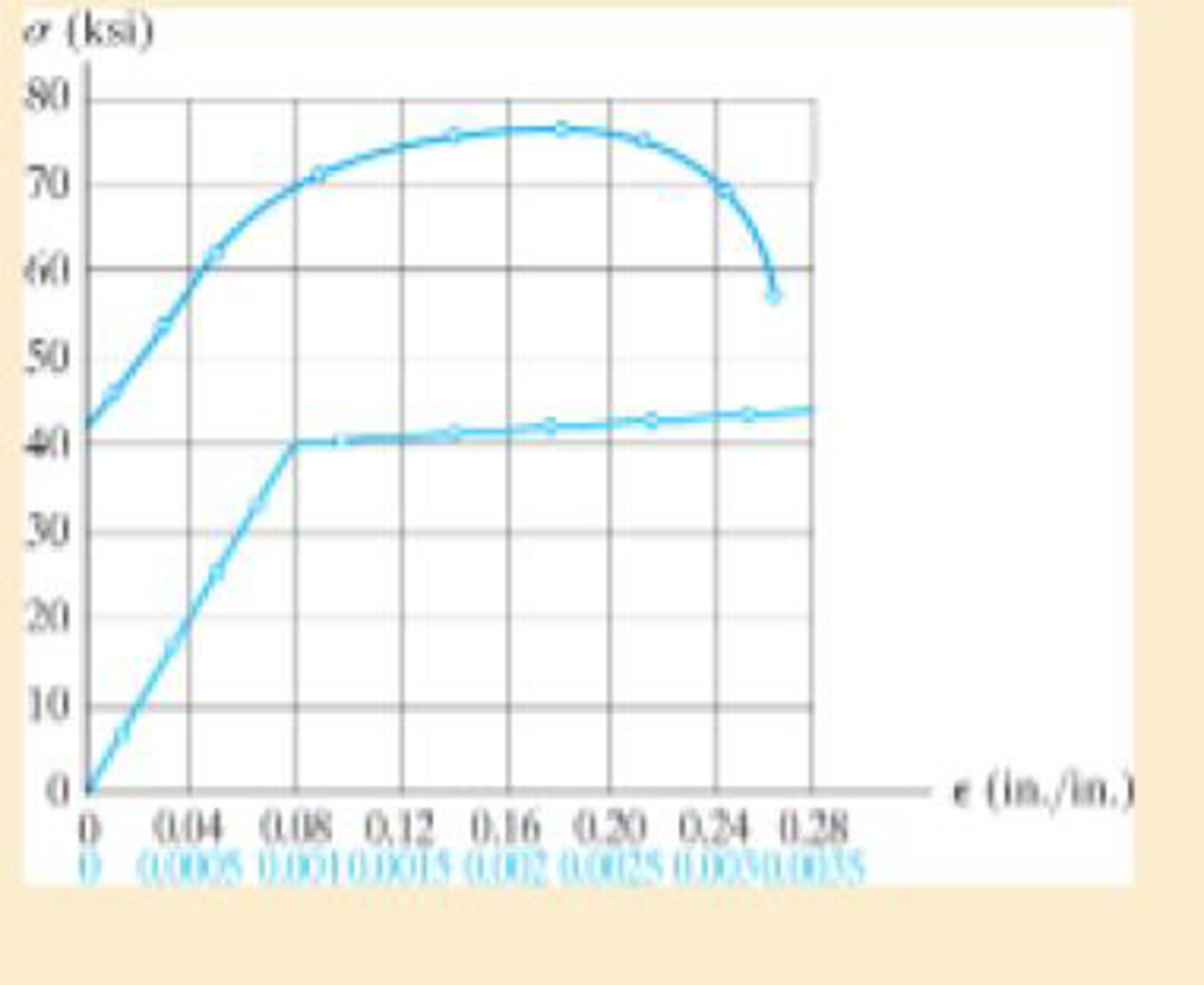
The stress-strain diagram for a steel alloy having an original diameter of 0.5 in. and a gage length of 2 in. is given in the figure. Determine approximately the modulus of elasticity for the material, the load on the specimen that causes yielding, and the ultimate load the specimen will support.
Prob. 3–4
Expert Solution & Answer
Want to see the full answer?
Check out a sample textbook solution
Students have asked these similar questions
8-21. The elastic portion of the stress-strain diagram for
an aluminum alloy is shown in the figure. The specimen
from which it was obtained has an original diameter of
12.7 mm and a gage length of 50.8 mm. When the applied
load on the specimen is 50 kN, the diameter is 12.67494 mm.
Determine Poisson's ratio for the material.
(MPa)
490
(mm/mm)
0.007
8-21. The elastic portion of the stress-strain diagram for
an aluminum alloy is shown in the figure. The specimen
from which it was obtained has an original diameter of
12.7 mm and a gage length of 50.8 mm. When the applied
load on the specimen is 50 kN, the diameter is 12.67494 mm.
Determine Poisson's ratio for the material.
8-22. The elastic portion of the stress-strain diagram for an
aluminum alloy is shown in the figure. The specimen from
which it was obtained has an original diameter of 12.7 mm
and a gage length of 50.8 mm. If a load of P = 60 kN is
applied to the specimen, determine its new diameter and
length. Take v = 0.35.
σ (MPa)
490
0.007
Probs. 8-21/22
€ (mm/mm)
The stress-strain diagram for an aluminum alloy that is used for making aircraft parts is shown in Figure. If a specimen of this material is stressed to s = 600 MPa, determine the permanent set that remains in the specimen when the load is released. Also, find the modulus of resilience both before and after the loan application.
Chapter 3 Solutions
STANDALONE CODE MECHANICS OF MATERIALS-M
Ch. 3.4 - Define a homogeneous material.Ch. 3.4 - Indicate the points on the stress-strain diagram...Ch. 3.4 - Define the modulus of elasticity E.Ch. 3.4 - At room temperature, mild steel is a ductile...Ch. 3.4 - Engineering stress and strain are calculated using...Ch. 3.4 - As the temperature increases the modulus of...Ch. 3.4 - A 100-mm-long rod has a diameter of 15 mm. If an...Ch. 3.4 - A bar has a length of 8 in. and cross-sectional...Ch. 3.4 - A 10-mm-diameter rod has a modulus of elasticity...Ch. 3.4 - The material for the 50-mm-long specimen has the...
Ch. 3.4 - The material for the 50-mm-long specimen has the...Ch. 3.4 - If the elongation of wire BC is 0.2 mm after the...Ch. 3.4 - Data taken from a stress-strain test for a ceramic...Ch. 3.4 - The stress-strain diagram for a steel alloy having...Ch. 3.4 - The stress-strain diagram for a steel alloy having...Ch. 3.4 - The stress-strain diagram for a steel alloy having...Ch. 3.4 - Determine the elongation of the square hollow bar...Ch. 3.4 - The stress-strain diagram for an aluminum alloy...Ch. 3.4 - The stress-strain diagram for an aluminum alloy...Ch. 3.4 - The stress-strain diagram for an aluminum alloy...Ch. 3.4 - A structural member in a nuclear reactor is made...Ch. 3.4 - The rigid pipe is supported by a pin at A and an...Ch. 3.4 - The rigid pipe is supported by a pin at A and an...Ch. 3.4 - Direct tension indicators are sometimes used...Ch. 3.4 - A tension test was performed on a magnesium alloy...Ch. 3.4 - The stress-strain diagram for a bone is shown and...Ch. 3.4 - The two bars are made of a material that has the...Ch. 3.4 - The two bars are made of a material that has the...Ch. 3.7 - A 100-mm-long rod has a diameter of 15 mm. If an...Ch. 3.7 - A solid circular rod that is 600 mm long and 20 mm...Ch. 3.7 - A 20-mm-wide block is firmly bonded to rigid...Ch. 3.7 - A 20-mm-wide block is bonded to rigid plates at...Ch. 3.7 - The acrylic plastic rod is 400mm long and 20mm in...Ch. 3.7 - The elastic portion of the stress-strain diagram...Ch. 3.7 - The elastic portion of the stress-strain diagram...Ch. 3.7 - The lap joint is connected together using a 1.25...Ch. 3.7 - The lap joint is connected together using a 1.25...Ch. 3.7 - Prob. 32PCh. 3.7 - The thin-walled tube is subjected to an axial...Ch. 3 - The elastic portion of the tension stress-strain...Ch. 3 - The elastic portion of the tension stress-strain...Ch. 3 - The rigid beam rests in the horizontal position on...Ch. 3 - The wires each have a diameter of 12 in., length...Ch. 3 - Prob. 5RPCh. 3 - diameter steel bolts. If the clamping force in...Ch. 3 - The stress-strain diagram for polyethylene, which...Ch. 3 - The pipe with two rigid caps attached to its ends...Ch. 3 - The 8-mm-diameter bolt is made of an aluminum...Ch. 3 - An acetal polymer block is fixed to the rigid...
Knowledge Booster


Learn more about
Need a deep-dive on the concept behind this application? Look no further. Learn more about this topic, mechanical-engineering and related others by exploring similar questions and additional content below.Similar questions
- The stress-strain diagram for a steel alloy having an original diameter of 0.5 in. and a gage length of 2 in. is given in the figure. Determine approximately the modulus of elasticity for the material, the load on the specimen that causes yielding, and the ultimate load the specimen will support. o (ksi) 80 70 60 50 40 30 20 10 e (in./in.) 0 0.04 0.08 0.12 0.16 0.20 0.24 0.28 0 .0.0005 0.0010.0015 0.002 0.0025 0.0030.0035arrow_forwardThe elastic portion of the stress–strain diagram for an aluminum alloy is shown in the figure. The specimen from which it was obtained has an original diameter of 12.7 mm and a gage length of 50.8 mm. If a load of P = 60 kN is applied to the specimen, determine its new diameter and length. Taken = 0.35.arrow_forwardThe stress–strain diagram for a steel alloy having an original diameter of 0.5 in. and a gage length of 2 in. is given in the figure. If the specimen is loaded until it is stressed to 70 ksi, determine the approximate amount of elasticrecovery and the increase in the gage length after it is unloaded.arrow_forward
- Problem 7 The shear stress-strain diagram for an alloy is shown in the figure. If a bolt having a diameter of 0.25 in. is made of this material and used in the lap joint, determine the modulus of elasticity E and the force P required to cause the material to yield. Take v=0.3. 7 (ksi) Ty= 50 0.004 y (rad)arrow_forwardThe shear stress–strain diagram for an alloy is shown in the figure. If a bolt having a diameter of 0.25 in. is made of this material and used in the lap joint, determine the modulus of elasticity E and the force P required to cause the material to yield. Take n = 0.3.arrow_forwardA steel cylinder bar is attached to the top end as it is subjected to three axial forces as shown in the figure. The rod diameter is 10 mm and the steel modulus of elasticity is 200 GN. Determine the total deformation in the steel rod. Use the last two digits of your ID for force F1. ID No. F1 = 30N 25 cm F,=? = 30N 15 cm 10 cm F;= 400 N F;=800 Narrow_forward
- Let's consider a rod having a solid circular cross-section with diameter of 6 mm and it is made of a material having a Young's modulus E = 200 Gpa and a Poisson's ratio of 0.3. If a tensile force F is subjected to that rod cross-section, the diameter becomes 5.995 mm. determine the applied force F. Select one: O F=15708N O F= 10472 N O F=5236 N O F= 13090 N O F=6283 N O F=4189 Narrow_forwardLet's consider a rod having a solid circular cross-section with diameter of 6 mm and it is made of a material having a Young's modulus E = 200 Gpa and a Poisson's ratio of 0.3. If a tensile force Fis subjected to that rod cross-section, the diameter becomes 5.998 mm. determine the applied force F. Select one: O F=15708 N O F= 5236 N O F= 6283 N O F=4189 N O F= 10472 N O F= 13090N Clear my choice Finish attempt. IOUS ACTIVITY 360 Test - Spring 2020-2021 Jump to. 11:21 PM 4) G ENG 4/15/2021 LEGO ort sc delete end home backspace num lock 7V home enter 4E K pause Marrow_forwardLet’s consider a rod having a solid circular cross-section with diameter of 6 mm and it is made of a material having a Young’s modulus E = 200 Gpa and a Poisson’s ratio of 0.3. If a tensile force F is subjected to that rod cross-section, the diameter becomes 5.998 mm. determine the applied force F. Select one: F = 6283 N F = 10472 N F = 4189 N F = 5236 N F = 13090 N F = 15708 Narrow_forward
- The elastic portion of the stress-strain diagram for an aluminum alloy is shown in the figure. The specimen from which it was obtained has an original diameter of 12.7 mm and a gage length of 50.8 mm. If a load of P=60 kN is applied to the specimen, determine its new diameter and length. Take v = 0.35. o (MPa) 490 e (mm/mm) 0.007arrow_forwardLet's consider a rod having a solid circular cross-section with diameter of 4 mm and it is made of a material having a Young's modulus E = 200 Gpa and a Poisson's ratio of 0.3. If a tensile force F is subjected to that rod cross-section, the diameter becomes 3.995 mm. determine the applied force F. Select one: F = 10472 N O F = 6283N O F= 15708 N O F = 4189N O F = 5236 N O F = 13090 N Clear my choicearrow_forwardThe stress-strain diagram for an aluminum alloy specimen having an original diameter of 0.5 in. and a gauge length of 2 in. is given in the figure. If the specimen is loaded until it is stressed to 60 ksi, determine the approximate amount of elastic recovery and the increase in the gage length after it is unloaded.arrow_forward
arrow_back_ios
SEE MORE QUESTIONS
arrow_forward_ios
Recommended textbooks for you
 Mechanics of Materials (MindTap Course List)Mechanical EngineeringISBN:9781337093347Author:Barry J. Goodno, James M. GerePublisher:Cengage Learning
Mechanics of Materials (MindTap Course List)
Mechanical Engineering
ISBN:9781337093347
Author:Barry J. Goodno, James M. Gere
Publisher:Cengage Learning
Lec21, Part 5, Strain transformation; Author: Mechanics of Materials (Libre);https://www.youtube.com/watch?v=sgJvz5j_ubM;License: Standard Youtube License