
Mechanics of Materials
9th Edition
ISBN: 9780133254426
Author: Russell C. Hibbeler
Publisher: Prentice Hall
expand_more
expand_more
format_list_bulleted
Videos
Textbook Question
Chapter 3.5, Problem 3.2FP
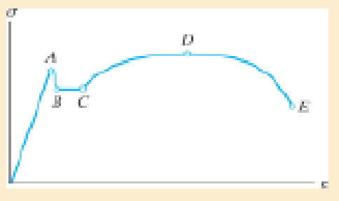
Indicate the points on the stress-strain diagram which represent the proportional limit and the ultimate stress.
Expert Solution & Answer
Want to see the full answer?
Check out a sample textbook solution
Students have asked these similar questions
Indicate the points on the stress-strain diagram which represent the proportional limit and the ultimate stress.
The state of stress at the point can also be represented in termsof the maximum in-plane shear stress.True or False?
• When the state of stress is represented by the principal stresses, no shear stress will act on the element. True or False?
Chapter 3 Solutions
Mechanics of Materials
Ch. 3.5 - Define a homogeneous material.Ch. 3.5 - Indicate the points on the stress-strain diagram...Ch. 3.5 - Define the modulus of elasticity E.Ch. 3.5 - At room temperature, mild steel is a ductile...Ch. 3.5 - Engineering stress and strain are calculated using...Ch. 3.5 - As the temperature increases the modulus of...Ch. 3.5 - A 100-mm-long rod has a diameter of 15 mm. If an...Ch. 3.5 - A bar has a length of 8 in. and cross-sectional...Ch. 3.5 - A 10-mm-diameter rod has a modulus of elasticity...Ch. 3.5 - The material for the 50-mm-long specimen has the...
Ch. 3.5 - The material for the 50-mm-long specimen has the...Ch. 3.5 - If the elongation of wire BC is 0.2 mm after the...Ch. 3.5 - A tension test was performed on a steel specimen...Ch. 3.5 - Data taken from a stress-strain test for a ceramic...Ch. 3.5 - Data taken from a stress-strain test for a ceramic...Ch. 3.5 - Prob. 3.4PCh. 3.5 - 3-5. A tension test was performed on a steel...Ch. 3.5 - 3-6. A specimen is originally 1 ft long, has a...Ch. 3.5 - Prob. 3.7PCh. 3.5 - Prob. 3.8PCh. 3.5 - 3-9. The ?-? diagram for elastic fibers that make...Ch. 3.5 - Prob. 3.10PCh. 3.5 - Prob. 3.11PCh. 3.5 - Prob. 3.12PCh. 3.5 - A bar having a length of 5 in. and cross-sectional...Ch. 3.5 - The rigid pipe is supported by a pin at A and an...Ch. 3.5 - Prob. 3.15PCh. 3.5 - Prob. 3.16PCh. 3.5 - Prob. 3.17PCh. 3.5 - Prob. 3.18PCh. 3.5 - The stress-strain diagram for a bone is shown, and...Ch. 3.5 - The stress-strain diagram for a bone is shown and...Ch. 3.5 - The two bars are made of a material that has the...Ch. 3.5 - The two bars are made of a material that has the...Ch. 3.5 - Prob. 3.23PCh. 3.5 - Prob. 3.24PCh. 3.8 - A 100-mm-long rod has a diameter of 15 mm. If an...Ch. 3.8 - A solid circular rod that is 600 mm long and 20 mm...Ch. 3.8 - A 20-mm-wide block is firmly bonded to rigid...Ch. 3.8 - A 20-mm-wide block is bonded to rigid plates at...Ch. 3.8 - The acrylic plastic rod is 200 mm long and 15 mm...Ch. 3.8 - 3–26. The thin-walled tube is subjected to an...Ch. 3.8 - 3-27. When the two forces are placed on the beam,...Ch. 3.8 - Prob. 3.28PCh. 3.8 - Prob. 3.29PCh. 3.8 - The lap joint is connected together using a 1.25...Ch. 3.8 - The lap joint is connected together using a 1.25...Ch. 3.8 - Prob. 3.32PCh. 3.8 - Prob. 3.33PCh. 3.8 - A shear spring is made from two blocks of rubber,...Ch. 3 - The elastic portion of the tension stress-strain...Ch. 3 - The elastic portion of the tension stress-strain...Ch. 3 - The rigid beam rests in the horizontal position on...Ch. 3 - The wires each have a diameter of 12 in., length...Ch. 3 - The wires each have a diameter of 12 in., length...Ch. 3 - diameter steel bolts. If the clamping force in...Ch. 3 - The stress-strain diagram for polyethylene, which...Ch. 3 - The pipe with two rigid caps attached to its ends...Ch. 3 - The 8-mm-diameter bolt is made of an aluminum...Ch. 3 - An acetal polymer block is fixed to the rigid...
Knowledge Booster


Learn more about
Need a deep-dive on the concept behind this application? Look no further. Learn more about this topic, mechanical-engineering and related others by exploring similar questions and additional content below.Similar questions
- 20) If the area under the stress and strain curve is more then it is concluded that the material has high stress Select one: True Falsearrow_forwardDo the principal stresses represent the maximum and minimum normal stress?arrow_forwardAt room temperature (20°C), a 0.5-mm gap exists between the ends of the rods shown. The temperature eventually reaches a value of 139°C. Determine the normal stress in the aluminum rod.arrow_forward
- The yield stress for a zirconium-magnesium alloy is sY = 15.3 ksi. If a machine part is made of this material and a critical point in the material is subjected to in-plane principal stresses s1 and s2 = -0.5s1, determine the magnitude of s1 that will cause yielding according to the maximum shear stress theory.arrow_forwardOn what does the magnitude of the stress components depend at a point?arrow_forwardAt room temperature (20°C), a 0.5-mm gap exists between the ends of the rods shown. The temperature eventually reaches a value of 140°C. Determine the normal stress in the aluminum rod. Determine the change in length of the aluminum rod.arrow_forward
- a-Shows the state of stress (three dimensional) at a point Q within a given stressed body. b- Briefly describe the three normal stress components and the six shear stress components of the stress at point Q.arrow_forwardA single strain gage forming an angle = 18° with a horizontal plane is used to determine the gage pressure in the cylindrical steel tank shown. The cylindrical wall of the tank is 6 mm thick, has a 600-mm inside diameter, and is made of a steel with E= 200 GPa and v = 0.30. Determine the pressure in the tank indicated by a strain gage reading of 320μ. (Round the final answer to three decimal places.) The pressure in the tank is MPa.arrow_forwardThe ratio of direct stress to the volumetric strain is known as Bulk Modulus Select one: True Falsearrow_forward
- Question 1A rod with a diameter of 30 mm and a length of 600 mm is subjected to an axial force of 60 kN which causes an elongation of 0.30 mm. Determine the stress in the rod, the strain, and the modulus of elasticity of the material.arrow_forwardDetermine the principal stresses, the maximum in-plane shear stress, and average normal stress. Specify the orientation of the element in each case.arrow_forwardTo determine the nominal or engineering stress and strain experienced by a specimen of a material while it is subjected to a tension test, and to be able to read important values from a conventional stress-strain diagram obtained from the test.A tension test is being conducted on a steel-rod specimen with a gauge length of L0=2 in and initial diameter of d0=0.5 in. Data were collected to form the conventional stress-strain diagram as shown. From the diagram, f = 73.0 ksi , e = 101.0 ksi g=83.0ksi, and h=0.15in/in Part A - Nominal or engineering strain in the rod Assuming that the strain remains constant throughout the region between the gauge points, determine the nominal strain ε experienced by the rod if it is elongated to L = 2.5 in . Express the nominal strain in inches per inch to three significant figures. Part B - Nominal or engineering stress in the specimen Assuming that the stress is constant over the cross-sectional area and if the tension force used is P = 8.0 kips ,…arrow_forward
arrow_back_ios
SEE MORE QUESTIONS
arrow_forward_ios
Recommended textbooks for you
 Mechanics of Materials (MindTap Course List)Mechanical EngineeringISBN:9781337093347Author:Barry J. Goodno, James M. GerePublisher:Cengage Learning
Mechanics of Materials (MindTap Course List)
Mechanical Engineering
ISBN:9781337093347
Author:Barry J. Goodno, James M. Gere
Publisher:Cengage Learning
Lec21, Part 5, Strain transformation; Author: Mechanics of Materials (Libre);https://www.youtube.com/watch?v=sgJvz5j_ubM;License: Standard Youtube License