
Bundle: Physics for Scientists and Engineers, Volume 2, Loose-leaf Version, 10th + WebAssign Printed Access Card for Serway/Jewett's Physics for Scientists and Engineers, 10th, Multi-Term
10th Edition
ISBN: 9781337888752
Author: Raymond A. Serway; John W. Jewett
Publisher: Cengage Learning
expand_more
expand_more
format_list_bulleted
Concept explainers
Videos
Textbook Question
Chapter 36, Problem 41AP
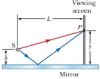
Interference fringes are produced using Lloyd’s mirror and a source S of wavelength λ = 606 nm as shown in Figure P36.41. Fringes separated by Δy = 1.20 mm are formed on a screen a distance L = 2.00 m from the source. Find the vertical distance h of the source above the reflecting surface.
Figure P36.41
Expert Solution & Answer

Trending nowThis is a popular solution!

Students have asked these similar questions
Interference effects are produced at point P on a screen as a result of direct rays from a 5.00 x 10² - nm source and reflected rays off a mirror, as shown in Figure P24.67. If the source is L = 1.00 x 10² m to the left of the screen and h = 1.00 cm above the mirror, find the distance y (in millimeters) to the first dark band above the mirror.
A lens made of glass (ng =1.52) is coated with a thin film of MgF2 (ns = 1.38) of thickness t. Visible light is incident normally on the coated lens as in Figure P24.30. (a) For what minimum value of t will the reflected light of wavelength 5.40 x 10² nm (in air) be missing? (b) Are there other values of t that will minimize the reflected light at this wavelength? Explain.
White light is incident normally on a glass lens (n=1.52) that is coated with a film of MgF2 (n=1.38). For what minimum thickness of the film will the reflections at the two interfaces result in total destructive interference of yellow light of wavelength 580 nm (in air)?
Chapter 36 Solutions
Bundle: Physics for Scientists and Engineers, Volume 2, Loose-leaf Version, 10th + WebAssign Printed Access Card for Serway/Jewett's Physics for Scientists and Engineers, 10th, Multi-Term
Ch. 36.2 - Which of the following causes the fringes in a...Ch. 36.3 - Using Figure 36.6 as a model, sketch the...Ch. 36.5 - One microscope slide is placed on top of another...Ch. 36 - Two slits are separated by 0.320 mm. A beam of...Ch. 36 - Why is the following situation impossible? Two...Ch. 36 - A laser beam is incident on two slits with a...Ch. 36 - In a Youngs double-slit experiment, two parallel...Ch. 36 - Light of wavelength 620 nm falls on a double slit,...Ch. 36 - Light with wavelength 442 nm passes through a...Ch. 36 - A student holds a laser that emits light of...
Ch. 36 - A student holds a laser that emits light of...Ch. 36 - Coherent light rays of wavelength strike a pair...Ch. 36 - In Figure P36.10 (not to scale), let L = 1.20 m...Ch. 36 - You are working in an optical research laboratory....Ch. 36 - You are operating a new radio telescope that has...Ch. 36 - In the double-slit arrangement of Figure P36.13, d...Ch. 36 - Monochromatic light of wavelength is incident on...Ch. 36 - Prob. 15PCh. 36 - Show that the distribution of intensity in a...Ch. 36 - Green light ( = 546 nm) illuminates a pair of...Ch. 36 - Monochromatic coherent light of amplitude E0 and...Ch. 36 - A material having an index of refraction of 1.30...Ch. 36 - A soap bubble (n = 1.33) floating in air has the...Ch. 36 - A film of MgF2 (n = 1.38) having thickness 1.00 ...Ch. 36 - An oil film (n = 1.45) floating on water is...Ch. 36 - When a liquid is introduced into the air space...Ch. 36 - You are working as an expert witness for an...Ch. 36 - Astronomers observe the chromosphere of the Sun...Ch. 36 - A lens made of glass (ng = 1.52) is coated with a...Ch. 36 - Mirror M1 in Figure 36.13 is moved through a...Ch. 36 - Radio transmitter A operating at 60.0 MHz is 10.0...Ch. 36 - In an experiment similar to that of Example 36.1,...Ch. 36 - In the What If? section of Example 36.2, it was...Ch. 36 - Two coherent waves, coming from sources at...Ch. 36 - Raise your hand and hold it flat. Think of the...Ch. 36 - In a Youngs double-slit experiment using light of...Ch. 36 - Review. A flat piece of glass is held stationary...Ch. 36 - Figure P36.35 shows a radio-wave transmitter and a...Ch. 36 - Figure P36.35 shows a radio-wave transmitter and a...Ch. 36 - In a Newtons-rings experiment, a plano-convex...Ch. 36 - Measurements are made of the intensity...Ch. 36 - A plano-concave lens having index of refraction...Ch. 36 - Why is the following situation impossible? A piece...Ch. 36 - Interference fringes are produced using Lloyds...Ch. 36 - A plano-convex lens has index of refraction n. The...Ch. 36 - Prob. 43APCh. 36 - Prob. 44APCh. 36 - Astronomers observe a 60.0-MHz radio source both...Ch. 36 - Prob. 46CPCh. 36 - Our discussion of the techniques for determining...Ch. 36 - The condition for constructive interference by...Ch. 36 - Both sides of a uniform film that has index of...Ch. 36 - Slit 1 of a double-slit is wider than slit 2 so...
Knowledge Booster


Learn more about
Need a deep-dive on the concept behind this application? Look no further. Learn more about this topic, physics and related others by exploring similar questions and additional content below.Similar questions
- In a Newtons-rings experiment, a plano-convex glass (n = 1.52) lens having radius r = 5.00 cm is placed on a flat plate as shown in Figure P36.37. When light of wavelength = 650 nm is incident normally, 55 bright rings are observed, with the last one precisely on the edge of the lens. (a) What is the radius R of curvature of the convex surface of the lens? (b) What is the focal length of the lens? Figure P36.37arrow_forwardIn the double-slit arrangement of Figure P36.13, d = 0.150 mm, L = 140 cm, = 643 nm. and y = 1.80 cm. (a) What is the path difference for the rays from the two slits arriving at P? (b) Express this path difference in terms of . (c) Does P correspond to a maximum, a minimum, or an intermediate condition? Give evidence for your answer. Figure P36.13arrow_forwardA beam of 580-nm light passes through two closely spaced glass plates at close to normal incidence as shown in Figure P27.23. For what minimum nonzero value of the plate separation d is the transmitted light bright?arrow_forward
- Table P35.80 presents data gathered by students performing a double-slit experiment. The distance between the slits is 0.0700 mm, and the distance to the screen is 2.50 m. The intensity of the central maximum is 6.50 106 W/m2. What is the intensity at y = 0.500 cm? TABLE P35.80arrow_forwardThe lens of a camera has a thin film coating designed to enhance the ability of the lens to absorb visible light near the middle of the spectrum, specifically light of wavelength 560 nm. If nair = 1.00, nfilmcoating = 1.40, and nlens = 1.55, what is the required minimum thickness of the film coating? Assume that the light is normally incident in the air medium. a. 250 nm b. 100 nm c. 150 nm d. 300 nm e. 200 nmarrow_forwardInterference effects are produced at point P on a screen as a result of direct rays from a 500-nm source and reflected rays offa mirror, as shown in Figure P24.67. If the source is L = 100 m to the left of the screen and h = 1.00 cm above the mirror, find the distance y (in millimeters) to the first dark band above the mirror.arrow_forward
- A plano-convex lens rests with its curved side on a flat glass surface and is illuminated from above by light of wavelength 464 nm. A dark spot is observed at the center, surrounded by 19 concentric dark rings (with bright rings in between). How much thicker is the air wedge at the position of the 19th dark ring than at the center? 2.41 um 2.97 um 3.77 um 4.41 umarrow_forwardA plano-concave lens having index of refraction 1.50 is placed on a flat glass plate as shown in Figure P36.39. Its curved surface, with radius of curvature 8.00 m, is on the bottom. The lens is illuminated from above with yellow sodium light of wavelength 589 nm, and a series of concentric bright and dark rings is observed by reflection. The interference pattern has a dark spot at the center that is surrounded by 50 dark rings, the largest of which is at the outer edge of the lens. (a) What is the thickness of the air layer at the center of the interference pattern? (b) Calculate the radius of the outermost dark ring. (c) Find the focal lengthof the lens.arrow_forwardIn Figure P36.10 (not to scale), let L = 1.20 m and d = 0.120 mm and assume the slit system is illuminated with monochromatic 500-nm light. Calculate the phase difference between the two wave fronts arriving at P when (a) = 0.500 and (b) y = 5.00 mm. (c) What is the value of for which the phase difference is 0.333 rad? (d) What is the value of for which the path difference is /4? Figure P36.10arrow_forward
- Figure P36.53 shows two thin glass plates separated by a wire with a square cross section of side length w, forming an air wedge between the plates. What is the edge length w of the wire if 42 dark fringes are observed from above when 589-nm light strikes the wedge at normal incidence? FIGURE P36.53arrow_forwardCoherent light rays of wavelength strike a pair of slits separated by distance d at an angle 1, with respect to the normal to the plane containing the slits as shown in Figure P27.14. The rays leaving the slits make an angle 2 with respect to the normal, and an interference maximum is formed by those rays on a screen that is a great distance from the slits. Show that the angle 2 is given by 2=sin1(sin1md) where m is an integer.arrow_forwardIn Figure P27.7 (not to scale), let L = 1.20 m and d = 0.120 mm and assume the slit system is illuminated with monochromatic 500-nm light. Calculate the phase difference between the two wave fronts arriving at P when (a) = 0.500 and (b) y = 5.00 mm. (c) What is the value of for which the phase difference is 0.333 rad? (d) What is the value of for which the path difference is /4?arrow_forward
arrow_back_ios
arrow_forward_ios
Recommended textbooks for you
 Physics for Scientists and Engineers with Modern ...PhysicsISBN:9781337553292Author:Raymond A. Serway, John W. JewettPublisher:Cengage Learning
 Physics for Scientists and EngineersPhysicsISBN:9781337553278Author:Raymond A. Serway, John W. JewettPublisher:Cengage Learning
 Principles of Physics: A Calculus-Based TextPhysicsISBN:9781133104261Author:Raymond A. Serway, John W. JewettPublisher:Cengage Learning
 Physics for Scientists and Engineers: Foundations...PhysicsISBN:9781133939146Author:Katz, Debora M.Publisher:Cengage Learning
Physics for Scientists and Engineers with Modern ...
Physics
ISBN:9781337553292
Author:Raymond A. Serway, John W. Jewett
Publisher:Cengage Learning
Physics for Scientists and Engineers
Physics
ISBN:9781337553278
Author:Raymond A. Serway, John W. Jewett
Publisher:Cengage Learning
Principles of Physics: A Calculus-Based Text
Physics
ISBN:9781133104261
Author:Raymond A. Serway, John W. Jewett
Publisher:Cengage Learning
Physics for Scientists and Engineers: Foundations...
Physics
ISBN:9781133939146
Author:Katz, Debora M.
Publisher:Cengage Learning
Diffraction of light animation best to understand class 12 physics; Author: PTAS: Physics Tomorrow Ambition School;https://www.youtube.com/watch?v=aYkd_xSvaxE;License: Standard YouTube License, CC-BY