
Mechanics of Materials Plus Mastering Engineering with Pearson eText - Access Card Package (10th Edition)
10th Edition
ISBN: 9780134518121
Author: Russell C. Hibbeler
Publisher: PEARSON
expand_more
expand_more
format_list_bulleted
Concept explainers
Videos
Textbook Question
Chapter 3.7, Problem 3.14FP
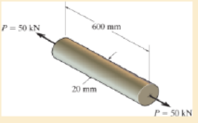
A solid circular rod that is 600 mm long and 20 mm in diameter is subjected to an axial force of P= 50 kN. The elongation of the rod is δ = 1.40 mm, and its diameter becomes d′ = 19.9837 mm. Determine the modulus of elasticity and the modulus of rigidity of the material. Assume that the material does not yield.
Expert Solution & Answer
Want to see the full answer?
Check out a sample textbook solution
Students have asked these similar questions
The rigid lever arm is supported by two A-36 steel wires having the same diameter of 4 mm. Determine the smallest force P that will cause (a) only one of the wires to yield; (b) both wires to yield. Consider A-36 steel as anelastic perfectly plastic material.
Rigid bar ABC is supported by bronze rod (1) and aluminum rod (2), as shown. A concentrated load P is applied to the free end of aluminum rod (3). Bronze rod (1) has an elastic modulus of E1 = 15,000 ksi and a diameter of d1 = 0.50 in. Aluminum rod (2) has an elastic modulus of E2 = 10,000 ksi and a diameter of d2 = 0.85in. Aluminum rod (3) has a diameter of d3 = 1.00in. The yield strength of the bronze is 48 ksi and the yield strength of the aluminum is 40 ksi. Assume a = 2.5 ft, b = 1.5 ft, L1 = 6 ft, L2 = 8 ft, and L3 = 3 ft.
(A) Calculate the cross-sectional areas of the three rods. in in.2
(B) For a factor of safety of 2.1, calculate the allowable stresses in the bronze and the aluminum rods. IN KSI.
(C) What is the magnitude of load P that can safely be applied to the structure for a minimum factor of safety of 2.1? in kips
(D) The pin used at B has an ultimate shear strength of 58 ksi. If a factor of safety of 2.5 is required, determine the allowable shear stress in this pin.…
Rigid bar ABC is supported by bronze rod (1) and aluminum rod (2), as shown. A concentrated load P is applied to the free end of aluminum rod (3). Bronze rod (1) has an elastic modulus of E1 = 15,000 ksi and a diameter of d1 = 0.40 in. Aluminum rod (2) has an elastic modulus of E2 = 10,000 ksi and a diameter of d2 = 0.70in. Aluminum rod (3) has a diameter of d3 = 1.00in. The yield strength of the bronze is 48 ksi and the yield strength of the aluminum is 40 ksi. Assume a = 2.5 ft, b = 1.5 ft, L1 = 6 ft, L2 = 8 ft, and L3 = 3 ft.
Chapter 3 Solutions
Mechanics of Materials Plus Mastering Engineering with Pearson eText - Access Card Package (10th Edition)
Ch. 3.4 - Define a homogeneous material.Ch. 3.4 - Indicate the points on the stress-strain diagram...Ch. 3.4 - Define the modulus of elasticity E.Ch. 3.4 - At room temperature, mild steel is a ductile...Ch. 3.4 - Engineering stress and strain are calculated using...Ch. 3.4 - As the temperature increases the modulus of...Ch. 3.4 - A 100-mm-long rod has a diameter of 15 mm. If an...Ch. 3.4 - A bar has a length of 8 in. and cross-sectional...Ch. 3.4 - A 10-mm-diameter rod has a modulus of elasticity...Ch. 3.4 - The material for the 50-mm-long specimen has the...
Ch. 3.4 - The material for the 50-mm-long specimen has the...Ch. 3.4 - If the elongation of wire BC is 0.2 mm after the...Ch. 3.4 - A tension test was performed on a steel specimen...Ch. 3.4 - Data taken from a stress-strain test for a ceramic...Ch. 3.4 - Data taken from a stress-strain test for a ceramic...Ch. 3.4 - The stress-strain diagram for a steel alloy having...Ch. 3.4 - The stress-strain diagram for a steel alloy having...Ch. 3.4 - The stress-strain diagram for a steel alloy having...Ch. 3.4 - The rigid beam is supported by a pin at C and an...Ch. 3.4 - The rigid beam is supported by a pin at C and an...Ch. 3.4 - Acetal plastic has a stress-strain diagram as...Ch. 3.4 - The stress-strain diagram for an aluminum alloy...Ch. 3.4 - The stress-strain diagram for an aluminum alloy...Ch. 3.4 - The stress-strain diagram for an aluminum alloy...Ch. 3.4 - A bar having a length of 5 in. and cross-sectional...Ch. 3.4 - The rigid pipe is supported by a pin at A and an...Ch. 3.4 - The rigid pipe is supported by a pin at A and an...Ch. 3.4 - Direct tension indicators are sometimes used...Ch. 3.4 - The rigid beam is supported by a pin at C and an...Ch. 3.4 - The rigid beam is supported by a pin at C and an...Ch. 3.4 - The stress-strain diagram for a bone is shown, and...Ch. 3.4 - The stress-strain diagram for a bone is shown and...Ch. 3.4 - The two bars are made of a material that has the...Ch. 3.4 - The two bars are made of a material that has the...Ch. 3.4 - The pole is supported by a pin at C and an A-36...Ch. 3.4 - The bar DA is rigid and is originally held in the...Ch. 3.7 - A 100-mm-long rod has a diameter of 15 mm. If an...Ch. 3.7 - A solid circular rod that is 600 mm long and 20 mm...Ch. 3.7 - A 20-mm-wide block is firmly bonded to rigid...Ch. 3.7 - A 20-mm-wide block is bonded to rigid plates at...Ch. 3.7 - The acrylic plastic rod is 200 mm long and 15 mm...Ch. 3.7 - The plug has a diameter of 30 mm and fits within a...Ch. 3.7 - The elastic portion of the stress-strain diagram...Ch. 3.7 - The elastic portion of the stress-strain diagram...Ch. 3.7 - The brake pads for a bicycle tire are made of...Ch. 3.7 - The lap joint is connected together using a 1.25...Ch. 3.7 - The lap joint is connected together using a 1.25...Ch. 3.7 - The rubber block is subjected to an elongation of...Ch. 3.7 - The shear stress-strain diagram for an alloy is...Ch. 3.7 - A shear spring is made from two blocks of rubber,...Ch. 3 - The elastic portion of the tension stress-strain...Ch. 3 - The elastic portion of the tension stress-strain...Ch. 3 - The rigid beam rests in the horizontal position on...Ch. 3 - The wires each have a diameter of 12 in., length...Ch. 3 - The wires each have a diameter of 12 in., length...Ch. 3 - diameter steel bolts. If the clamping force in...Ch. 3 - The stress-strain diagram for polyethylene, which...Ch. 3 - The pipe with two rigid caps attached to its ends...Ch. 3 - The 8-mm-diameter bolt is made of an aluminum...Ch. 3 - An acetal polymer block is fixed to the rigid...
Knowledge Booster


Learn more about
Need a deep-dive on the concept behind this application? Look no further. Learn more about this topic, mechanical-engineering and related others by exploring similar questions and additional content below.Similar questions
- A 10-mm-diameter rod has a modulus of elasticity of E = 100GPa. If it is 4 m long and subjected to an axial tensile load of 6 kN, determine its elongation. Assume linear elastic behavior.arrow_forwardA straight bar 450 mm long is 10 mm in diameter for the first 200 mm length and 20 mm in diameter for the remaining length. If the bar is subjected to an axial push of 10 kN, determine decrease in length of the bar. Take modulus of elasticity of bar material E = 2 × 10⁵ N/mm²arrow_forwardA tensile load of 50, 000 lb is applied to a metal bar with a 0.6 in x 0.6 in. cross section and a gage length of 2 in. Under this load the bar elastically deforms so that the gage length increases to 2.007 in. and the cross section decreases to 0.599 in. x 0.599 in. Determine the modulus of elasticity and Poisson’s ratio for this metal.arrow_forward
- A plastic rod is 200mm long and 15mm in diameter. If a tensile load of 300N is applied to it, determine the change in its length and the change in its diameter. Assume Modulus of elasticity (E) = 2.70 GPa, and poisson's ratio (v) = 0.4. indicate free body diagramarrow_forwardA force P and a force Q, applied via a nut, are acting on the arm attached to the end of a shaft made of steel. The strain gauge readings on point A of the shaft show the following deformation values: ε1 = 630x10-6, ε2 = 600x10-6, and ε3 = - 189x10-6. Determine the magnitudes of the applied forces P and Q (E = 200 GPa, υ = 0.3).arrow_forwardA 100-mm-long rod has a diameter of 15 mm. If an axial tensile load of 100 kN is applied, determine its change in length. Assume linear elastic behavior with E = 200 GPa.arrow_forward
- A loading condition is shown below. The wires at point A and D both made from a steel with the yield strength (Sy) of 190 MPa with 2 mm diameter. Using either maximum shear stress theory or distortion energy theory, determine the maximum load P that can be applied before yielding happens in the wires.arrow_forwardThe wires each have a diameter of 2 cm, length of 6 m, and aremade from a material with modulus of elasticity ? = 19.3 GPa.If three external loadings are applied to the rigid beam AC,determine the angle of tilt of the rigid beam. Assume thedeformation of the wires obeys the Hooke’s lawarrow_forwardA solid circular rod that is 600 mm long and 20 mm in diameter is subjected to an axial force of P = 50 kN. The elongation of the rod is d = 1.40 mm, and its diameter becomes d = 19.9837 mm. Determine the modulus of elasticity and the modulus of rigidity of the material. Assume that the material does not yield.arrow_forward
- A solid steel post having a length of 3m and a diameter of 80 mm is subjected to pure torsion. a) What is the torsional rigidity of the post if the shear modulus of elasticity is 80 GPa? b) Determine the torsional stiffness of the steel post. c) Determine the maximum shear stress in the steel post if it is subjected to a torque of 612 N-m.arrow_forwardA large water tank that has a capacity to carry 20,000 liters is to be supported by four cylindrical posts. These four support posts are made of plain carbon (1045) steels with the yield and tensile strengths of 310 MPa and 565 MPa, respectively. Determine the minimum required diameter of the post assuming a factor of safety of 5.arrow_forwardA 100-mm long rod has a diameter of 15 mm. If an axial tensile load of 165 kN is applied, determine its change in length. Assume linear-elastic behavior with E = 200 GPa.arrow_forward
arrow_back_ios
SEE MORE QUESTIONS
arrow_forward_ios
Recommended textbooks for you
 Mechanics of Materials (MindTap Course List)Mechanical EngineeringISBN:9781337093347Author:Barry J. Goodno, James M. GerePublisher:Cengage Learning
Mechanics of Materials (MindTap Course List)
Mechanical Engineering
ISBN:9781337093347
Author:Barry J. Goodno, James M. Gere
Publisher:Cengage Learning
EVERYTHING on Axial Loading Normal Stress in 10 MINUTES - Mechanics of Materials; Author: Less Boring Lectures;https://www.youtube.com/watch?v=jQ-fNqZWrNg;License: Standard YouTube License, CC-BY