
MECHANICS OF MATERIALS (LOOSE)-W/ACCESS
10th Edition
ISBN: 9780134583228
Author: HIBBELER
Publisher: PEARSON
expand_more
expand_more
format_list_bulleted
Videos
Textbook Question
Chapter 3.7, Problem 3.33P
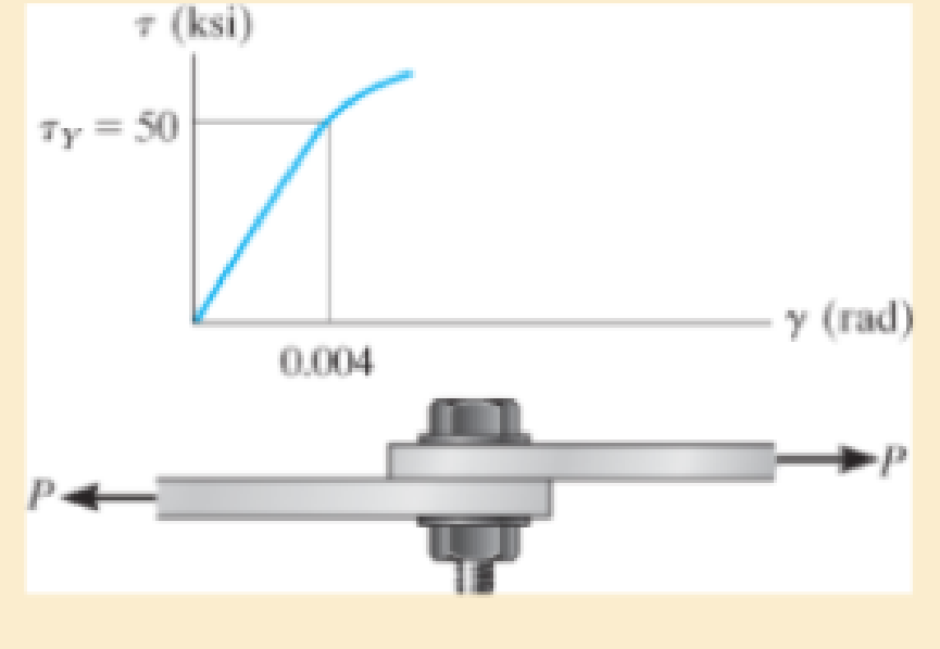
The shear stress-strain diagram for an alloy is shown in the figure. If a bolt having a diameter of 0.25 in. is made of this material and used in the lap joint, determine the modulus of elasticity E and the force P required to cause the material to yield. Take v = 0.3.
Expert Solution & Answer

Learn your wayIncludes step-by-step video

schedule04:53
Students have asked these similar questions
The shear stress–strain diagram for an alloy is shown in the figure. If a bolt having a diameter of 0.25 in. is made of this material and used in the lap joint, determine the modulus of elasticity E and the force P required to cause the material to yield. Take n = 0.3.
The stress-strain diagram for an aluminum alloy specimen having an original diameter of 0.5 in. and a gauge length of 2 in. is given in the figure. If the specimen is loaded until it is stressed to 60 ksi, determine the approximate amount of elastic recovery and the increase in the gage length after it is unloaded.
Assuming that the load P = 120 KN is carried equally by the four rivets in the figure showing the double lap connection, determine the following: (a) the shear stress in the rivets if the diameter of the rivet is 16 mm and (b) the thickness of the inner steel plate if the bearing stress is132.63 MPa.
Chapter 3 Solutions
MECHANICS OF MATERIALS (LOOSE)-W/ACCESS
Ch. 3.4 - Define a homogeneous material.Ch. 3.4 - Indicate the points on the stress-strain diagram...Ch. 3.4 - Define the modulus of elasticity E.Ch. 3.4 - At room temperature, mild steel is a ductile...Ch. 3.4 - Engineering stress and strain are calculated using...Ch. 3.4 - As the temperature increases the modulus of...Ch. 3.4 - A 100-mm-long rod has a diameter of 15 mm. If an...Ch. 3.4 - A bar has a length of 8 in. and cross-sectional...Ch. 3.4 - A 10-mm-diameter rod has a modulus of elasticity...Ch. 3.4 - The material for the 50-mm-long specimen has the...
Ch. 3.4 - The material for the 50-mm-long specimen has the...Ch. 3.4 - If the elongation of wire BC is 0.2 mm after the...Ch. 3.4 - A tension test was performed on a steel specimen...Ch. 3.4 - Data taken from a stress-strain test for a ceramic...Ch. 3.4 - Data taken from a stress-strain test for a ceramic...Ch. 3.4 - The stress-strain diagram for a steel alloy having...Ch. 3.4 - The stress-strain diagram for a steel alloy having...Ch. 3.4 - The stress-strain diagram for a steel alloy having...Ch. 3.4 - The rigid beam is supported by a pin at C and an...Ch. 3.4 - The rigid beam is supported by a pin at C and an...Ch. 3.4 - Acetal plastic has a stress-strain diagram as...Ch. 3.4 - The stress-strain diagram for an aluminum alloy...Ch. 3.4 - The stress-strain diagram for an aluminum alloy...Ch. 3.4 - The stress-strain diagram for an aluminum alloy...Ch. 3.4 - A bar having a length of 5 in. and cross-sectional...Ch. 3.4 - The rigid pipe is supported by a pin at A and an...Ch. 3.4 - The rigid pipe is supported by a pin at A and an...Ch. 3.4 - Direct tension indicators are sometimes used...Ch. 3.4 - The rigid beam is supported by a pin at C and an...Ch. 3.4 - The rigid beam is supported by a pin at C and an...Ch. 3.4 - The stress-strain diagram for a bone is shown, and...Ch. 3.4 - The stress-strain diagram for a bone is shown and...Ch. 3.4 - The two bars are made of a material that has the...Ch. 3.4 - The two bars are made of a material that has the...Ch. 3.4 - The pole is supported by a pin at C and an A-36...Ch. 3.4 - The bar DA is rigid and is originally held in the...Ch. 3.7 - A 100-mm-long rod has a diameter of 15 mm. If an...Ch. 3.7 - A solid circular rod that is 600 mm long and 20 mm...Ch. 3.7 - A 20-mm-wide block is firmly bonded to rigid...Ch. 3.7 - A 20-mm-wide block is bonded to rigid plates at...Ch. 3.7 - The acrylic plastic rod is 200 mm long and 15 mm...Ch. 3.7 - The plug has a diameter of 30 mm and fits within a...Ch. 3.7 - The elastic portion of the stress-strain diagram...Ch. 3.7 - The elastic portion of the stress-strain diagram...Ch. 3.7 - The brake pads for a bicycle tire are made of...Ch. 3.7 - The lap joint is connected together using a 1.25...Ch. 3.7 - The lap joint is connected together using a 1.25...Ch. 3.7 - The rubber block is subjected to an elongation of...Ch. 3.7 - The shear stress-strain diagram for an alloy is...Ch. 3.7 - A shear spring is made from two blocks of rubber,...Ch. 3 - The elastic portion of the tension stress-strain...Ch. 3 - The elastic portion of the tension stress-strain...Ch. 3 - The rigid beam rests in the horizontal position on...Ch. 3 - The wires each have a diameter of 12 in., length...Ch. 3 - The wires each have a diameter of 12 in., length...Ch. 3 - diameter steel bolts. If the clamping force in...Ch. 3 - The stress-strain diagram for polyethylene, which...Ch. 3 - The pipe with two rigid caps attached to its ends...Ch. 3 - The 8-mm-diameter bolt is made of an aluminum...Ch. 3 - An acetal polymer block is fixed to the rigid...
Additional Engineering Textbook Solutions
Find more solutions based on key concepts
What parts are included in the vehicle chassis?
Automotive Technology: Principles, Diagnosis, And Service (6th Edition) (halderman Automotive Series)
The free body diagram of the ring at A. The magnitude of force in each cable.
Engineering Mechanics: Statics & Dynamics (14th Edition)
Use Mohrs circle to determine the normal stress and shear stress acting on the inclined plane AB.
Statics and Mechanics of Materials (5th Edition)
Calculate the mass of a can of oil if it weighs 610N.
Applied Fluid Mechanics (7th Edition)
3. The longest sea bridge, the Jiaozhou Bay Bridge in China, spans 26.4 miles [mi]. The longest sea bridge in t...
Thinking Like an Engineer: An Active Learning Approach (3rd Edition)
Knowledge Booster


Learn more about
Need a deep-dive on the concept behind this application? Look no further. Learn more about this topic, mechanical-engineering and related others by exploring similar questions and additional content below.Similar questions
- A copper bar with a square cross section is inserted into a square rigid tube as shown in the figure. The length of the copper bar is 1.2 m and the area of the cross section is 300 mm2. The bar is subjected to a force P that applies a uniformly distributed pressure to the copper. Calculate the force P if the longitudinal displacement of the bar is 2 mm. Assume that the modulus of elasticity of the bar is E = 110 GPa and Poisson’s ratio is v = 0.33. Disregard friction between the copper and the rigid tube.arrow_forwardSolve the preceding problem (W 250 × 44.8) if the resultant force P equals 110 kN and E = 200 GPa.arrow_forward, Solve the preceding problem using the numerical data: /) = 90mm, h = 280 mm, d = 210 mm, q = 14 kN/m, and L = L2 m.arrow_forward
- A steel bar has a square cross section of width b = 2.0 in. (sec figure). The bar has pinned supports at the ends and is 3.0 ft long. The axial forces acting at the end of the bar have a resultant P = 20 kips located at distance e = 0,75 in, from the center of the cross section. Also, the modulus of elasticity of the steel is 29,000 ksi. Determine the maximum compressive stress max, in the bar. If the allowable stress in the steel is 18,000 psi, what is the maximum permissible length Lmaxof the bar?arrow_forwardA short post constructed from a hollow circular tube of aluminum supports a compressive load of 54 kips. The inner and outer diameters of the tube are d1=3.6 in. and d2=5.0 in., respectively, and its length is 40 in. The shortening of the post due to the load is measured as 0.022 in. Determine the compressive stress and strain in the post. (Disregard the weight of the post itself, and assume that the post does not buckle under the load.) 5arrow_forwardThe elastic portion of the stress–strain diagram for an aluminum alloy is shown in the figure. The specimen from which it was obtained has an original diameter of 12.7 mm and a gage length of 50.8 mm. If a load of P = 60 kN is applied to the specimen, determine its new diameter and length. Taken = 0.35.arrow_forward
- The stress-strain diagram for a steel alloy having an original diameter of 0.5 in. and a gauge length of 2 in. is given in the figure. Determine approximately the modulus of elasticity for the material, the load on the specimen that causes yielding, and the ultimate load the specimen will support.arrow_forwardThe aluminum pipe shown in Figure is used to support a load of 150 kip. Determine the maximum displacement at the top of the pipe if the load is(a) applied gradually, and (b) applied by suddenly releasing it from the topof the pipe when h = 0. Take Eal = 10(103) ksi and assume that the aluminum behaves elastically.arrow_forwardThe stress–strain diagram for a steel alloy having an original diameter of 0.5 in. and a gage length of 2 in. is given in the figure. If the specimen is loaded until it is stressed to 70 ksi, determine the approximate amount of elasticrecovery and the increase in the gage length after it is unloaded.arrow_forward
- Strains measured in a, b and c directions are yardımıa=-150x10-6, ɛb=200x10-6, and ɛc=300x10-6 with the help of the rosette placed at point A of the elastic material under the effect of plane tension. Calculate the principal stresses since the modulus of elasticity in the material is E= 200 GPa and the Poisson ratio ν= 0.3arrow_forward6. A prismatic bar of length L is subjected to axial load P. Determine the maximum strain & along the bar length, given that the axial displacement along the member length varies according u = (12/L) × 10-3.arrow_forwardA bar made of A-36 steel has the dimensions shown in Figure. If an axial force of P = 80 kN is applied to the bar, determine the change in its length and the change in the dimensions of its cross-section. The material behaves elastically.arrow_forward
arrow_back_ios
SEE MORE QUESTIONS
arrow_forward_ios
Recommended textbooks for you
 Mechanics of Materials (MindTap Course List)Mechanical EngineeringISBN:9781337093347Author:Barry J. Goodno, James M. GerePublisher:Cengage Learning
Mechanics of Materials (MindTap Course List)
Mechanical Engineering
ISBN:9781337093347
Author:Barry J. Goodno, James M. Gere
Publisher:Cengage Learning
An Introduction to Stress and Strain; Author: The Efficient Engineer;https://www.youtube.com/watch?v=aQf6Q8t1FQE;License: Standard YouTube License, CC-BY