
Concept explainers
Videos
Use the superposition principle to find io and vo in the circuit of Fig. 4.79.
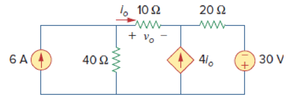
Figure 4.79
Find the value of the voltage
Answer to Problem 11P
The value of the voltage
Explanation of Solution
Given data:
Refer to Figure 4.79 in the textbook.
Calculation:
The circuit in Figure 4.79 involves a current-controlled current source, which must be left intact. Let
Where
To obtain
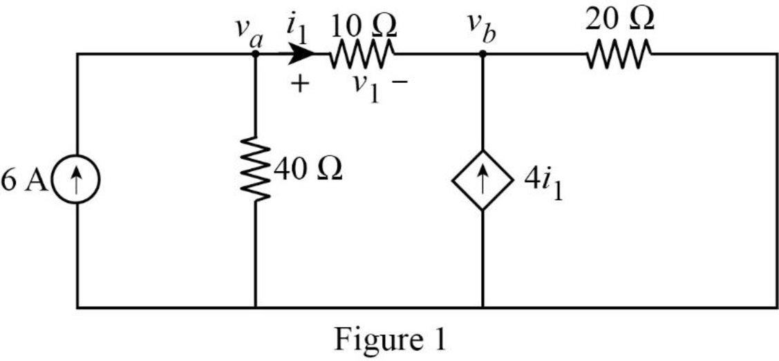
Apply nodal analysis at node
Apply nodal analysis at node
Rearranging the equation (3),
In Figure 1, the current
Substitute
Rearranging the equation (6),
Substitute
Rearrange the equation (8) to find the node voltage
Substitute
The voltage
Substitute
To obtain
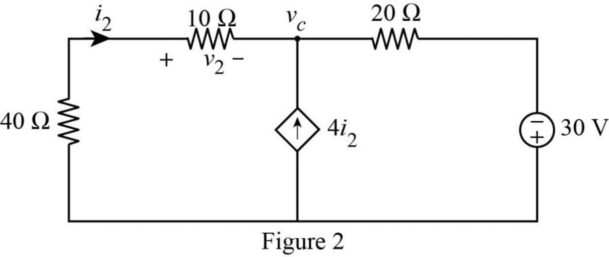
Apply nodal analysis at node
In Figure 2, the resistors 10 ohms and 40 ohms are connected in series. Therefore, the equivalent resistance for series connection is,
The modified circuit is shown in Figure 3.
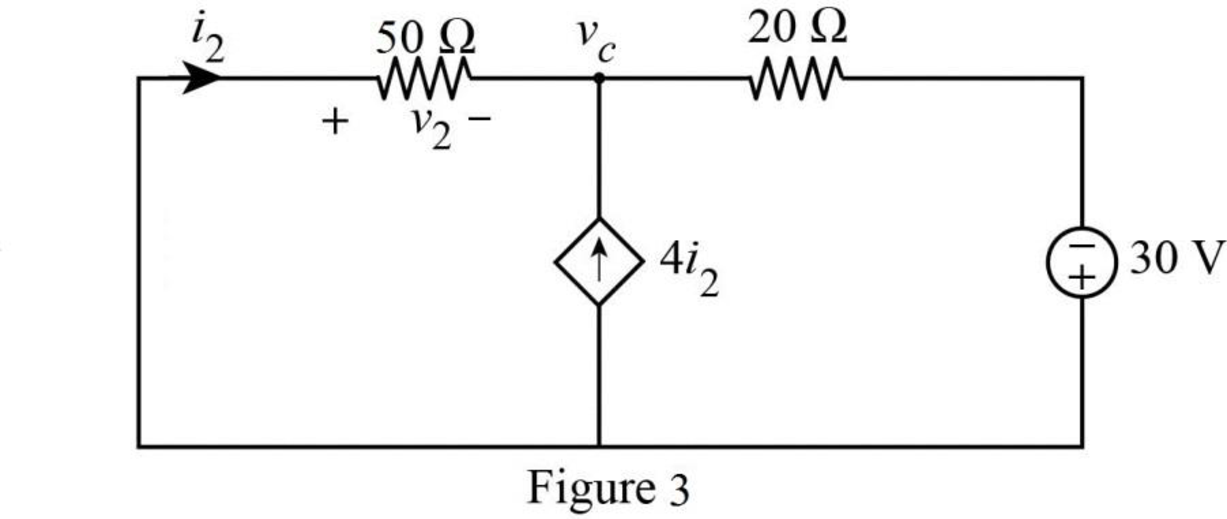
In Figure 3, the current
Substitute
The equation (12) becomes,
Rearrange the equation (13) to find the node voltage
Substitute
Therefore, in Figure 2 the voltage
Substitute
Substitute
In Figure 4.79, the current
PSPICE Simulation:
In the given circuit, since there are two sources, let
Where
When
Draw the circuit diagram in PSPICE as shown in Figure 4.
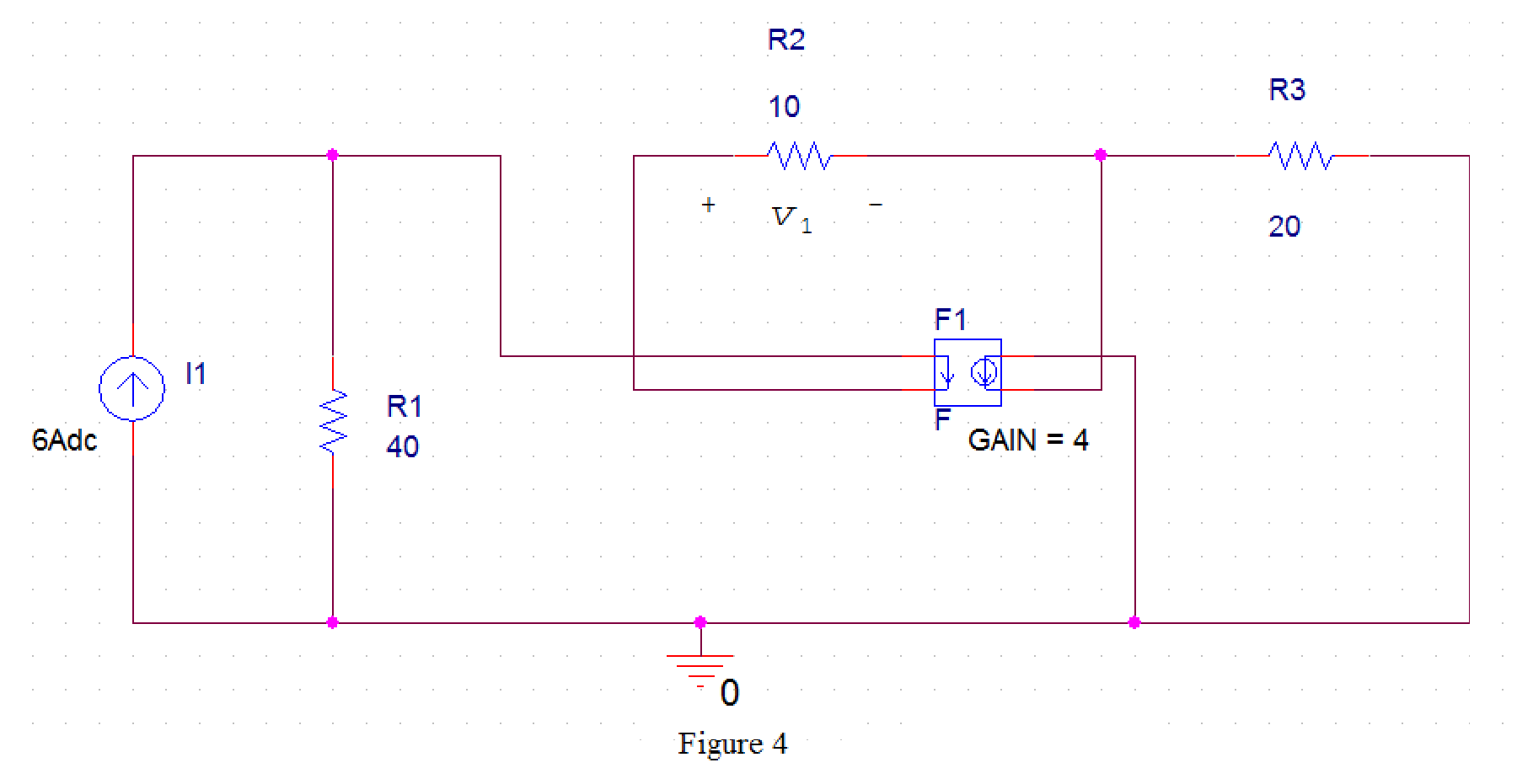
Save the circuit and provide the Simulation Settings as shown in Figure 5.
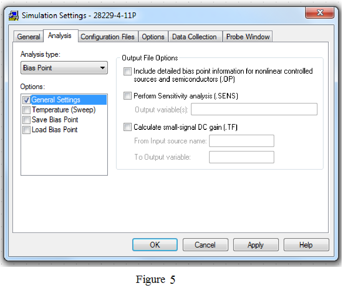
Now run the simulation and the results will be displayed as shown in Figure 6 by enabling “Enable Bias Voltage Display” icon and “Enable Bias Current Display” icon.
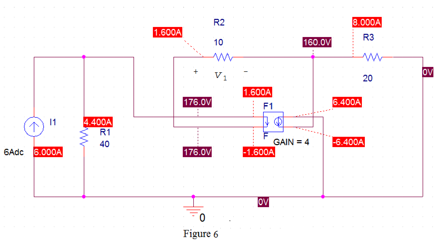
From Figure 6, the voltage
When
Draw the circuit diagram in PSPICE as shown in Figure 7.
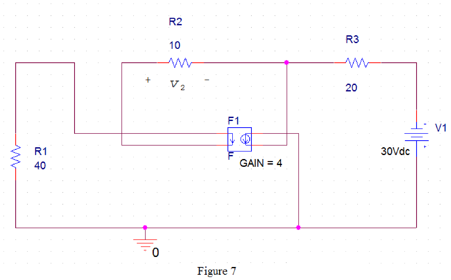
Save the circuit and provide the Simulation Settings as shown in Figure 8.
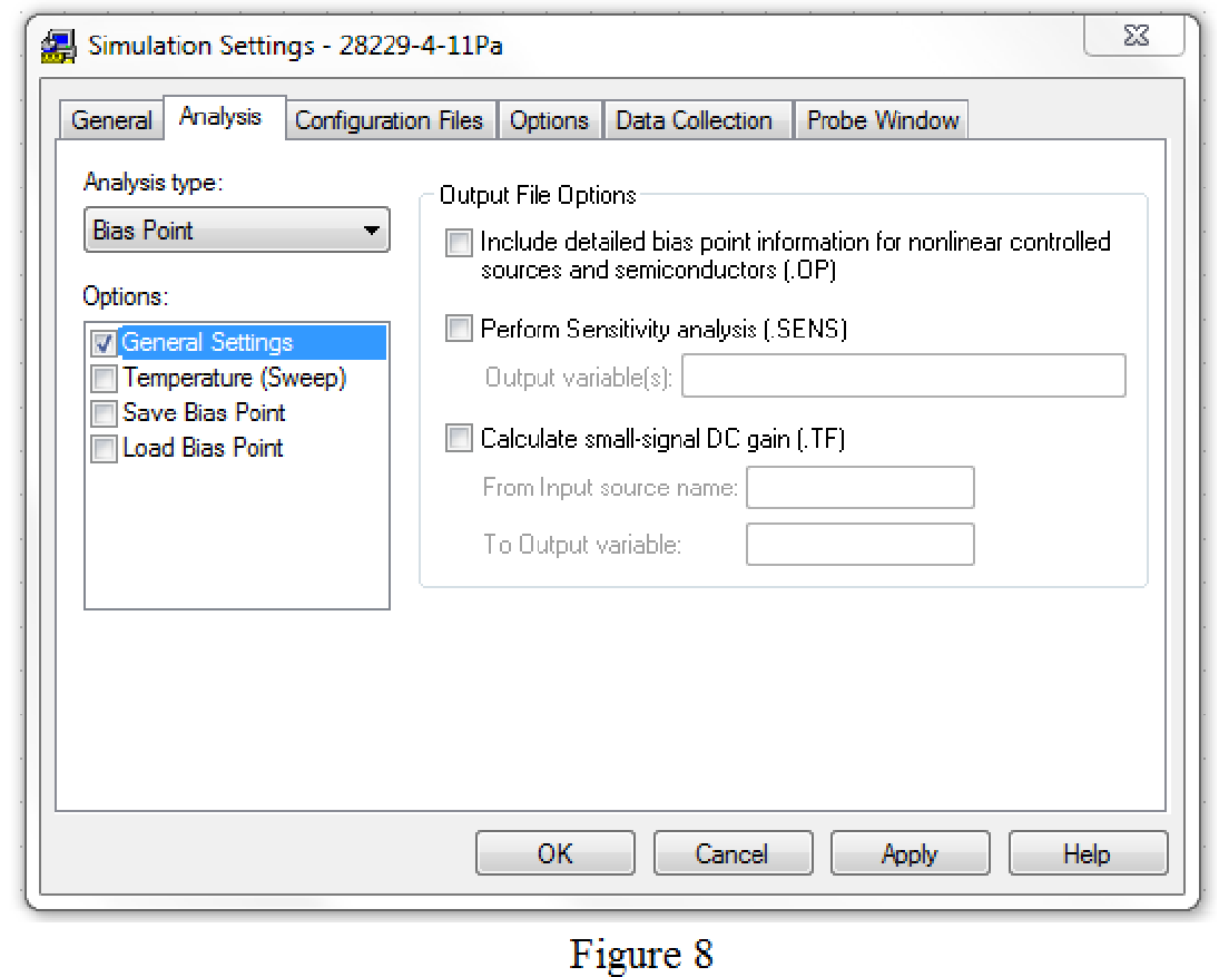
Now run the simulation and the results will be displayed as shown in Figure 9 by enabling “Enable Bias Voltage Display” icon and “Enable Bias Current Display” icon.
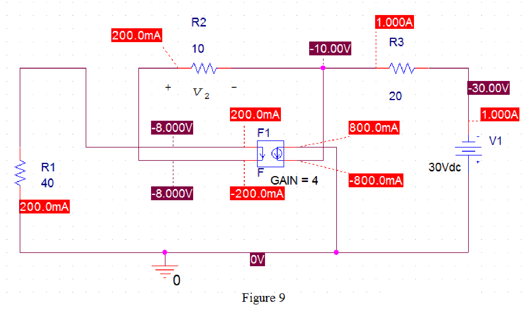
From Figure 9, the voltage
Therefore, the total voltage
Substitute
The current
Substitute 18 for
Conclusion:
Thus, the value of the voltage
Want to see more full solutions like this?
Chapter 4 Solutions
Fundamentals of Electric Circuits


- Question: 4.12 Determine vo in the circuit of Fig. 4.80 using the superposition principle.arrow_forward4.57 Obtain the Thevenin and Norton equivalent circuitsat terminals a-b for the circuit in Fig. 4.123.arrow_forwardDetermination Vth, Determination Rth, Thevenin equivalent circuit, Maximum Power.arrow_forward
- Using Thevenin’s theorem, find the equivalent circuit to the left of the terminals in the circuit of Fig. 4.30. Then find I.arrow_forwardNumber 4.29 Use source transformation to find correctly Vo in the circuit of Fig. 4.97.arrow_forwardUsing the superstition theorem, how would I prove the second images problem, given that #2 (voltage source was replaced with a short) measured 5 amps, and #4 (had the current source replaced with an open circuit) measured 1.6 amps?arrow_forward
- Using, necessarily, the superposition method, calculate the voltage that is applied on the terminals of the current source.arrow_forwardTeaching values through exhortation can be done with the help of ____________ a. Friends b. Computers c. Neighbors d. Stories with moral lessonsarrow_forward11 Kelvin Double Bridge is used for the measurement of larger value resistance. Select one: True Falsearrow_forward
 Introductory Circuit Analysis (13th Edition)Electrical EngineeringISBN:9780133923605Author:Robert L. BoylestadPublisher:PEARSON
 Delmar's Standard Textbook Of ElectricityElectrical EngineeringISBN:9781337900348Author:Stephen L. HermanPublisher:Cengage Learning
 Programmable Logic ControllersElectrical EngineeringISBN:9780073373843Author:Frank D. PetruzellaPublisher:McGraw-Hill Education
 Fundamentals of Electric CircuitsElectrical EngineeringISBN:9780078028229Author:Charles K Alexander, Matthew SadikuPublisher:McGraw-Hill Education
 Electric Circuits. (11th Edition)Electrical EngineeringISBN:9780134746968Author:James W. Nilsson, Susan RiedelPublisher:PEARSON
 Engineering ElectromagneticsElectrical EngineeringISBN:9780078028151Author:Hayt, William H. (william Hart), Jr, BUCK, John A.Publisher:Mcgraw-hill Education,