Fundamentals of Electric Circuits
6th Edition
ISBN: 9780078028229
Author: Charles K Alexander, Matthew Sadiku
Publisher: McGraw-Hill Education
bartleby

Videos

Textbook Question
Book Icon
Chapter 4, Problem 94CP

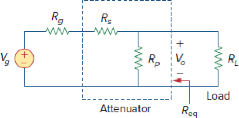
An attenuator is an interface circuit that reduces the voltage level without changing the output resistance.

  1. (a) By specifying Rs and Rp of the interface circuit in Fig. 4.150, design an attenuator that will meet the following requirements:

    V o V g = 0.125 , R eq = R Th = R g = 100 Ω

  2. (b) Using the interface designed in part (a), calculate the current through a load of RL = 50 Ω when Vg = 12 V.

Figure 4.150

Chapter 4, Problem 94CP, An attenuator is an interface circuit that reduces the voltage level without changing the output

(a)

Expert Solution
Check Mark
To determine

Find the value of the resistance Rs and Rp of the circuit shown in Figure 4.150.

Answer to Problem 94CP

The value of the resistance Rs is 700Ω and Rp is 114.29Ω in the given circuit.

Explanation of Solution

Given data:

Refer to Figure 4.150 in the textbook.

The voltage,

VoVg=0.125

The resistance,

Req=RTh=Rg=100Ω

Calculation:

In the given circuit, find the voltage Vo by removing the load resistor RL and the modified circuit is shown in Figure 1.

Fundamentals of Electric Circuits, Chapter 4, Problem 94CP , additional homework tip  1

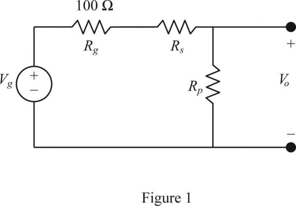
In Figure 1, the voltage Vo is calculated by using voltage division principle as follows.

Vo=(Vg)(RpRg+Rs+Rp)

VoVg=RpRg+Rs+Rp        (1)

Let us consider α=VoVg.

Substitute α for VoVg in equation (1) as follows.

α=RpRg+Rs+RpRpα=Rg+Rs+RpRpαRp=Rg+RsRp(1α1)=Rg+Rs

Simplify the equation as follows,

Rp(1αα)=Rg+Rs        (2)

Refer to Figure 4.150 in the textbook.

In the given circuit, find the Thevenin resistance by turning off the voltage source Vg (replace with a short circuit) and remove the load resistor RL and the modified circuit is shown in Figure 2.

Fundamentals of Electric Circuits, Chapter 4, Problem 94CP , additional homework tip  2

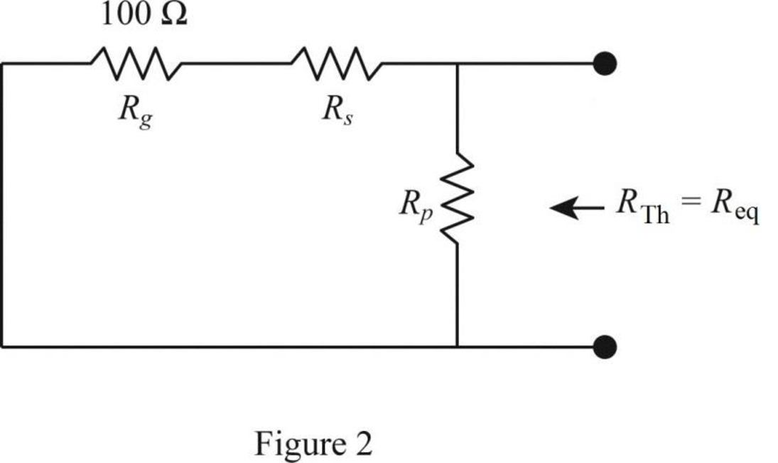
In Figure 2, the Thevenin resistance is,

RTh=(Rg+Rs)||(Rp)Rg=(Rg+Rs)(Rp)(Rg+Rs+Rp){RTh=Rg}RpRg+Rg2+RgRs=RpRg+RpRsRpRg+Rg2+RgRsRpRg=RpRs

Simplify the equation as follows,

Rg2+RgRs=RpRsRpRs=Rg(Rg+Rs)

RpRsRg=Rg+Rs        (3)

On comparing equation (2) and (3),

Rp(1αα)=RpRsRg

Rs=Rg(1αα)        (4)

Substitute 100 for Rg and 0.125 for α in equation (4) to find the value of resistance Rs in ohms.

Rs=100(10.1250.125){α=VoVg=0.125}=700Ω

Substitute 100 for Rg, 700 for Rs, and 0.125 for α in equation (2) to find the value of the resistance Rp in ohms.

Rp(10.1250.125)=100+700Rp(10.1250.125)=800Rp(7)=800Rp=114.29Ω

Conclusion:

Thus, the value of the resistance Rs is 700Ω and Rp is 114.29Ω in the given circuit.

(b)

Expert Solution
Check Mark
To determine

Find the current through the load resistor RL when Vg=12V.

Answer to Problem 94CP

The current through the load resistor RL is 10mA.

Explanation of Solution

Given data:

Refer to Figure 4.150 in the textbook.

The voltage Vg=12V.

The load resistor RL=50Ω.

The resistance,

Req=RTh=Rg=100Ω

The voltage,

VoVg=0.125        (5)

Calculation:

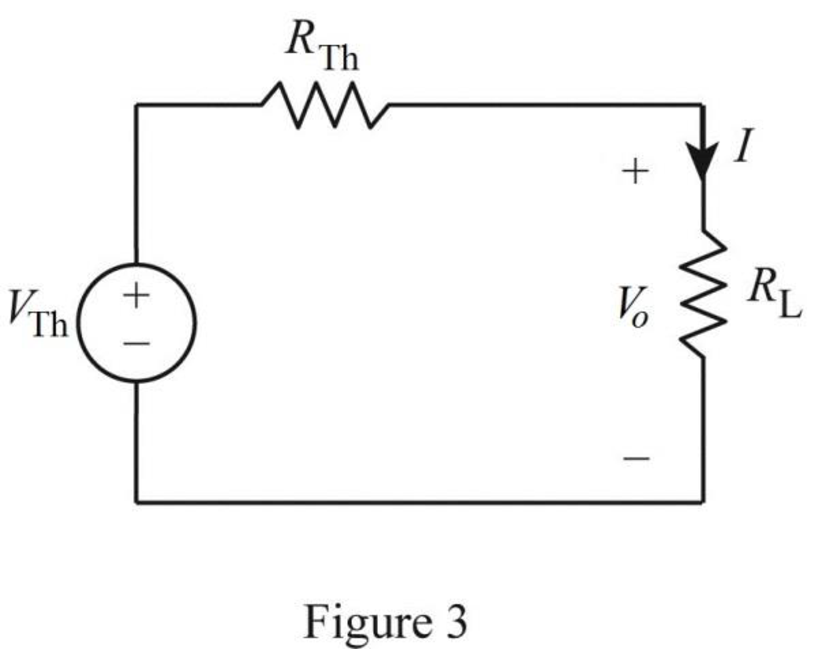
The Thevenin equivalent is shown in Figure 3.

Fundamentals of Electric Circuits, Chapter 4, Problem 94CP , additional homework tip  3

Rearrange the equation (5) as follows,

Vo=0.125Vg

Substitute 12 for Vg to find the voltage Vo in volts.

Vo=0.125×12=1.5V

In Figure 3, the voltage Vo is the Thevenin voltage. Therefore,

VTh=Vo=1.5V

In Figure 3, the current through the load resistor RL is calculated by using Ohm’s law as follows.

I=VThRTh+RL

Substitute 1.5 for VTh, 50 for RL, and 100 for RTh to find the current through the load resistor RL in amperes.

I=1.5100+50=0.01×103×103A=10mA{1m=103}

Conclusion:

Thus, the current through the load resistor RL is 10mA.

Want to see more full solutions like this?

Subscribe now to access step-by-step solutions to millions of textbook problems written by subject matter experts!
Students have asked these similar questions
the circuit shown in Fig.4, the current through 8Ω is *
The Maximum Power Transfer Theorem is an extremely useful method of analysis. circuits, defining the condition under which the maximum power is transferred from the source to the charge" . Relating to the statement, consider that a linear circuit was simplified using Norton's Theorem. Your structure can be represented according to the diagram below. In this way, determine the maximum power transferred by him.
For the network of Figure Q4 (b), Find vC, vx, ix and for t >0. Let vC (0) = 15 v.

Chapter 4 Solutions

Fundamentals of Electric Circuits

Ch. 4.6 - Find the Norton equivalent circuit for the circuit...Ch. 4.6 - Find the Norton equivalent circuit of the circuit...Ch. 4.8 - Determine the value of RL that will draw the...Ch. 4.9 - Rework Practice Prob. 4.9 using PSpice. Find the...Ch. 4.9 - Fin d the maximum power transferred to RL if the...Ch. 4.10 - The measured open-circuit voltage across a certain...Ch. 4.10 - Prob. 17PPCh. 4.10 - Obtain the current through the galvanometer,...Ch. 4 - The current through a branch in a linear network...Ch. 4 - For superposition, it is not required that only...Ch. 4 - The superposition principle applies to power...Ch. 4 - Refer to Fig. 4.67. The Thevenin resistance at...Ch. 4 - The Thevenin voltage across terminals a and b of...Ch. 4 - The Norton current at terminals a and b of the...Ch. 4 - The Norton resistance RN is exactly equal to the...Ch. 4 - Which pair of circuits in Fig. 4.68 are...Ch. 4 - A load is connected to a network. At the terminals...Ch. 4 - The source is supplying the maximum power to the...Ch. 4 - Calculate the current io in the circuit of Fig....Ch. 4 - Using Fig. 4.70, design a problem to help other...Ch. 4 - (a) In the circuit of Fig. 4.71, calculate vo and...Ch. 4 - Use linearity to determine io in the circuit of...Ch. 4 - For the circuit in Fig. 4.73, assume vo = 1 V, and...Ch. 4 - For the linear circuit shown in Fig. 4.74, use...Ch. 4 - Use linearity and the assumption that Vo = 1 V to...Ch. 4 - Using superposition, find Vo in the circuit of...Ch. 4 - Given that I = 6 amps when Vs = 160 volts and Is =...Ch. 4 - Using Fig. 4.78, design a problem to help other...Ch. 4 - Use the superposition principle to find io and vo...Ch. 4 - Determine vo in the circuit of Fig. 4.80 using the...Ch. 4 - Use superposition to find vo in the circuit of...Ch. 4 - Apply the superposition principle to find vo in...Ch. 4 - For the circuit in Fig. 4.83, use superposition to...Ch. 4 - Given the circuit in Fig. 4.84, use superposition...Ch. 4 - Use superposition to obtain vx in the circuit of...Ch. 4 - Use superposition to find Vo in the circuit of...Ch. 4 - Use superposition to solve for vx in the circuit...Ch. 4 - Use source transformation to reduce the circuit...Ch. 4 - Using Fig. 4.89, design a problem to help other...Ch. 4 - For the circuit in Fig, 4.90, use source...Ch. 4 - Referring to Fig. 4.91, use source transformation...Ch. 4 - Use source transformation to find the voltage Vx...Ch. 4 - Obtain vo in the circuit of Fig. 4.93 using source...Ch. 4 - Use source transformation to find io in the...Ch. 4 - Apply source transformation to find vx in the...Ch. 4 - Use source transformation to find Io in Fig. 4.96....Ch. 4 - Use source transformation to find vo in the...Ch. 4 - Use source transformation on the circuit shown in...Ch. 4 - Determine vx in the circuit of Fig. 4.99 using...Ch. 4 - Use source transformation to find ix in the...Ch. 4 - Determine the Thevenin equivalent circuit, shown...Ch. 4 - Using Fig. 4.102, design a problem that will help...Ch. 4 - Use Thevenins theorem to find vo in Prob. 4.12....Ch. 4 - Solve for the current i in the circuit of Fig....Ch. 4 - Find the Norton equivalent with respect to...Ch. 4 - Apply Thevenins theorem to find Vo in the circuit...Ch. 4 - Obtain the Thevenin equivalent at terminals a-b of...Ch. 4 - Find the Thevenin equivalent at terminals a-b of...Ch. 4 - Find the Thevenin and Norton equivalents at...Ch. 4 - For the circuit in Fig. 4.109, find the Thevenin...Ch. 4 - Find the Thevenin equivalent looking into...Ch. 4 - For the circuit in Fig. 4.111, obtain the Thevenin...Ch. 4 - Find the Thevenin equivalent of the circuit in...Ch. 4 - Using Fig. 4.113, design a problem to help other...Ch. 4 - Obtain the Thevenin and Norton equivalent circuits...Ch. 4 - Determine the Norton equivalent at terminals a-b...Ch. 4 - Find the Norton equivalent looking into terminals...Ch. 4 - Obtain the Norton equivalent of the circuit in...Ch. 4 - Given the circuit in Fig. 4.117, obtain the Norton...Ch. 4 - For the transistor model in Fig. 4.118, obtain the...Ch. 4 - Find the Norton equivalent at terminals a-b of the...Ch. 4 - Find the Thevenin equivalent between terminals a-b...Ch. 4 - Obtain the Norton equivalent at terminals a-b of...Ch. 4 - Use Nortons theorem to find Vo in the circuit of...Ch. 4 - Obtain the Thevenin and Norton equivalent circuits...Ch. 4 - The network in Fig. 4.124 models a bipolar...Ch. 4 - Determine the Thevenin and Norton equivalents at...Ch. 4 - For the circuit in Fig. 4.126, find the Thevenin...Ch. 4 - Obtain the Thevenin and Norton equivalent circuits...Ch. 4 - Find the Thevenin equivalent of the circuit in...Ch. 4 - Find the Norton equivalent for the circuit in Fig....Ch. 4 - Obtain the Thevenin equivalent seen at terminals...Ch. 4 - For the circuit shown in Fig. 4.131, determine the...Ch. 4 - Find the maximum power that can be delivered to...Ch. 4 - The variable resistor R in Fig. 4.133 is adjusted...Ch. 4 - Consider the 30- resistor in Fig. 4.134. First...Ch. 4 - Find the maximum power transferred to resistor R...Ch. 4 - Determine the maximum power delivered to the...Ch. 4 - For the circuit in Fig. 4.137, what resistor...Ch. 4 - (a) For the circuit in Fig. 4.138, obtain the...Ch. 4 - Determine the maximum power that can be delivered...Ch. 4 - For the bridge circuit shown in Fig. 4.140, find...Ch. 4 - For the circuit in Fig. 4.141, determine the value...Ch. 4 - Solve Prob. 4.34 using PSpice or MultiSim. Let V =...Ch. 4 - Use PSpice or MultiSim to solve Prob. 4.44. For...Ch. 4 - Use PSpice or MultiSim to solve Prob. 4.52.Ch. 4 - Obtain the Thevenin equivalent of the circuit in...Ch. 4 - Use PSpice or MultiSim to find the Thevenin...Ch. 4 - For the circuit in Fig. 4.126, use PSpice or...Ch. 4 - An automobile battery has an open circuit voltage...Ch. 4 - The following results were obtained from...Ch. 4 - When connected to a 4- resistor, a battery has a...Ch. 4 - The Thevenin equivalent at terminals a-b of the...Ch. 4 - A black box with a circuit in it is connected to a...Ch. 4 - A transducer is modeled with a current source Is...Ch. 4 - Consider the circuit in Fig. 4.144. An ammeter...Ch. 4 - Consider the circuit in Fig. 4.145. (a) Replace...Ch. 4 - The Wheatstone bridge circuit shown in Fig. 4.146...Ch. 4 - (a) In the Wheatstone bridge circuit of Fig. 4.147...Ch. 4 - Consider the bridge circuit of Fig. 4.148. Is the...Ch. 4 - The circuit in Fig. 4.149 models a common-emitter...Ch. 4 - An attenuator is an interface circuit that reduces...Ch. 4 - A dc voltmeter with a sensitivity of 10 k/V is...Ch. 4 - A resistance array is connected to a load resistor...Ch. 4 - A common-emitter amplifier circuit is shown in...Ch. 4 - For Practice Prob. 4.18, determine the current...
Knowledge Booster
Background pattern image
Electrical Engineering
Learn more about
Need a deep-dive on the concept behind this application? Look no further. Learn more about this topic, electrical-engineering and related others by exploring similar questions and additional content below.
Similar questions
SEE MORE QUESTIONS
Recommended textbooks for you
Text book image
Introductory Circuit Analysis (13th Edition)
Electrical Engineering
ISBN:9780133923605
Author:Robert L. Boylestad
Publisher:PEARSON
Text book image
Delmar's Standard Textbook Of Electricity
Electrical Engineering
ISBN:9781337900348
Author:Stephen L. Herman
Publisher:Cengage Learning
Text book image
Programmable Logic Controllers
Electrical Engineering
ISBN:9780073373843
Author:Frank D. Petruzella
Publisher:McGraw-Hill Education
Text book image
Fundamentals of Electric Circuits
Electrical Engineering
ISBN:9780078028229
Author:Charles K Alexander, Matthew Sadiku
Publisher:McGraw-Hill Education
Text book image
Electric Circuits. (11th Edition)
Electrical Engineering
ISBN:9780134746968
Author:James W. Nilsson, Susan Riedel
Publisher:PEARSON
Text book image
Engineering Electromagnetics
Electrical Engineering
ISBN:9780078028151
Author:Hayt, William H. (william Hart), Jr, BUCK, John A.
Publisher:Mcgraw-hill Education,
02 - Sinusoidal AC Voltage Sources in Circuits, Part 1; Author: Math and Science;https://www.youtube.com/watch?v=8zMiIHVMfaw;License: Standard Youtube License