Activities Manual for Programmable Logic Controllers
5th Edition
ISBN: 9781259679568
Author: Petruzella, Frank
Publisher: MCGRAW-HILL HIGHER EDUCATION
expand_more
expand_more
format_list_bulleted
Concept explainers
Question
Chapter 4, Problem 3P
Program Plan Intro
Logic gate:
- Logic gate is an electronic circuit that is used to perform logic decisions based on the input.
- It contains one or more number of inputs and one output.
- The working of logic gate is based on the binary principle that has two states either logic 0 or logic 1.
- The output of logic gate is produced when it satisfies any of its logic conditions.
- The logic condition depends upon the type of the gates and the number of inputs.
- The primary logic gates include AND, OR, and NOT. The combinations of these gates are used to implement any of the other logic gates.
AND gate:
- The AND gate refers to a logic gate whose output will be HIGH only when all the inputs are HIGH.
- The output of AND gate will be LOW when any one of its input will be LOW.
- The symbol to represent AND gate is given below:
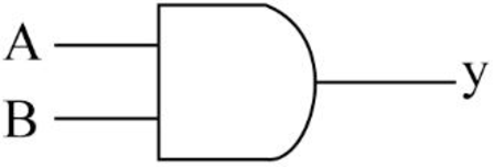
- The truth table for AND gate is as follows:
| INPUT A | INPUT B | OUTPUT Y |
| 0 | 0 | 0 |
| 0 | 1 | 0 |
| 1 | 0 | 0 |
| 1 | 1 | 1 |
NOR gate:
- NOR gate performs the inverse operation of OR gate.
- The NOR gate refers to a logic gate whose output will be HIGH only when all the inputs are LOW.
- The output of NOR gate will be LOW when any one of its input will be HIGH.
- The symbol to represent NOR gate is given below:
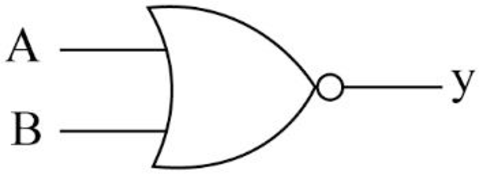
- The truth table for NOR gate is as follows:
| INPUT A | INPUT B | OUTPUT Y |
| 0 | 0 | 1 |
| 0 | 1 | 0 |
| 1 | 0 | 0 |
| 1 | 1 | 0 |
Expert Solution & Answer

Trending nowThis is a popular solution!

Students have asked these similar questions
3- Design the logic circuit for the following conditions and draw the
output wave form : X is a 0 if any two of the three variable A,B,
and C are 1X is a 1 for all other conditions ?
Problem: Derive the logic expressions for a circuit that compares two unsigned numbers:
X = x2x1xo and Y = = y2y1yo and generates three outputs: XGY, XEY, and XLY. One of these
outputs is set to 1 to indicate that X is greater than, equal to, or less than Y, respectively.
A
B
C
Figure Q3
1) implement the logic circuit using 8-to-1 multiplexer.
2) implement the logic circuit using 4-to-1 multiplexer.
3) implement the logic circuit using 2-to-1 multiplexer.
Chapter 4 Solutions
Activities Manual for Programmable Logic Controllers
Knowledge Booster


Learn more about
Need a deep-dive on the concept behind this application? Look no further. Learn more about this topic, computer-science and related others by exploring similar questions and additional content below.Similar questions
- PROBLEM: Given the Logic expression X = [(A+B) + (CC) ] [(CC) + (BOD)] (a.) Draw the Logic circuit and write the OUTPUT of EACH gate in a given table below. (b.) Connect the Logic Circuit in the TINKERCADD that you have drawn and write the output in a given table below. TRUTH TABLE: A B C D 0 0 0 0 0 0 0 1 0 0 1 0 0 0 1 1 0 1 0 0 0 1 0 1 0 1 1 0 0 1 1 1 0 0 0 1 0 1 1 1 0 1 1 1 1 0 0 1 0 1 1 1 0 1 1 1 0000 0 0 1 1 1 1arrow_forward2. Construct the truth table of a logic circuit having three inputs A, B, C, and the output Y is High(1) only in the case when at least 2 of the inputs are high(1).arrow_forward2. Write the Boolean expression of the given logic circuit as shown below. X. F =arrow_forward
- For the logic circuit given below, determine the Boolean expression for the output X, and construct the corresponding truth table.arrow_forwardQuestion 2 Write a boolean expression for the following combinational logic circuit and draw the truth table. A B. COMBINATIONAL CIRCUITS Score Blooms Designation АР b) Design a logic circuit with input signal A, control input B, and outputs X and Y to operate as follows: When B 1, output X will follow input A, and output Y will be 0. When B = 0, output X will be 0, and output Y will follow input A.arrow_forwardDevelop a logic circuit that will produce a 1 on its output only when all three inputs are 1s or when all three inputs are 0s.arrow_forward
- 1. Using the logic expression given below, draw the logic circuit using inverter (NOT gate), AND and OR gates. Draw properly and using the correct symbol. F = AB' + C'(B + D')arrow_forwardProblem 5. Write the Boolean expression (in Sum of Products form) for the logic circuit that will have a 1 output when X = 0, Y = 0, Z = 1 and X = 1, Y = 1, Z = 0, and a zero (0) output for all other input states. Draw the logic diagram for this circuit.arrow_forwardFind the logic expression for the output produced by the logic circuit given below. A Barrow_forward
- Part a Design a logic circuit using the truth table Inputs output shown. Use only basic logic gates (AND, OR, NOT). Also, the circuit should use the FEWEST number of gates and the FEWEST number of inputs to the gates. Fully label all the inputs and outputs. a b. 1 1 1 1 1. 1 1 Part b Implement a 3-input XOR gate using only a 4x1 multiplexer and an inverter. Also complete the truth table in your answer sheets with the correct labels and function solution. Fully label all inputs and outputs. Part c Design a full-adder using half-adders and A- additional logic using the half-adder shown here. Pi Giarrow_forwardWRITE THE LOGIC EQUATION CONTRUCT THE TRUTH TABLE LOGIC CIRCUIT (A) Iarrow_forward2. A sequential circuit with two D flip-flops A and B, two inputs X and Y, and one output Z is specified by the following input and output equations: DA = AX+XY DB = BX + XY Z = AB a b. . C Draw the logic diagram of the circuit Derive the state table for the circuit Derive the state diagram for the circuit.arrow_forward
arrow_back_ios
SEE MORE QUESTIONS
arrow_forward_ios
Recommended textbooks for you
 Database System ConceptsComputer ScienceISBN:9780078022159Author:Abraham Silberschatz Professor, Henry F. Korth, S. SudarshanPublisher:McGraw-Hill Education
 Starting Out with Python (4th Edition)Computer ScienceISBN:9780134444321Author:Tony GaddisPublisher:PEARSON
 Digital Fundamentals (11th Edition)Computer ScienceISBN:9780132737968Author:Thomas L. FloydPublisher:PEARSON
 C How to Program (8th Edition)Computer ScienceISBN:9780133976892Author:Paul J. Deitel, Harvey DeitelPublisher:PEARSON
 Database Systems: Design, Implementation, & Manag...Computer ScienceISBN:9781337627900Author:Carlos Coronel, Steven MorrisPublisher:Cengage Learning
 Programmable Logic ControllersComputer ScienceISBN:9780073373843Author:Frank D. PetruzellaPublisher:McGraw-Hill Education
Database System Concepts
Computer Science
ISBN:9780078022159
Author:Abraham Silberschatz Professor, Henry F. Korth, S. Sudarshan
Publisher:McGraw-Hill Education
Starting Out with Python (4th Edition)
Computer Science
ISBN:9780134444321
Author:Tony Gaddis
Publisher:PEARSON
Digital Fundamentals (11th Edition)
Computer Science
ISBN:9780132737968
Author:Thomas L. Floyd
Publisher:PEARSON
C How to Program (8th Edition)
Computer Science
ISBN:9780133976892
Author:Paul J. Deitel, Harvey Deitel
Publisher:PEARSON
Database Systems: Design, Implementation, & Manag...
Computer Science
ISBN:9781337627900
Author:Carlos Coronel, Steven Morris
Publisher:Cengage Learning
Programmable Logic Controllers
Computer Science
ISBN:9780073373843
Author:Frank D. Petruzella
Publisher:McGraw-Hill Education