
Concept explainers
Videos
Find the Thevenin equivalent at terminals a-b of the circuit in Fig. 4.107.
Figure 4.107
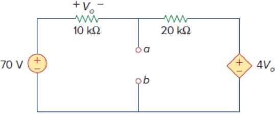
Find the Thevenin voltage and Thevenin resistance at terminals a-b of the circuit shown in Figure 4.107.
Answer to Problem 40P
The Thevenin voltage is
Explanation of Solution
Given data:
Refer to Figure 4.107 in the textbook.
The voltage source is
Calculation:
The given circuit is modified as shown in Figure 1.
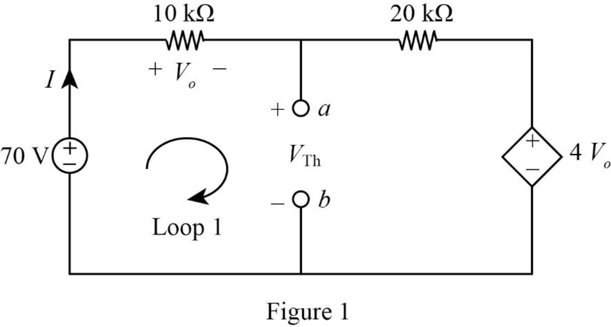
In Figure 1, apply Kirchhoff’s voltage law to the outer loop as follows,
In Figure 1, the voltage
Substitute equation (2) in equation (1),
Simplify the equation as follows,
In Figure 1, apply Kirchhoff’s voltage law to the Loop 1 as follows,
Substitute
In the given circuit, find the Thevenin resistance by turning off the
The modified circuit is shown in Figure 2.
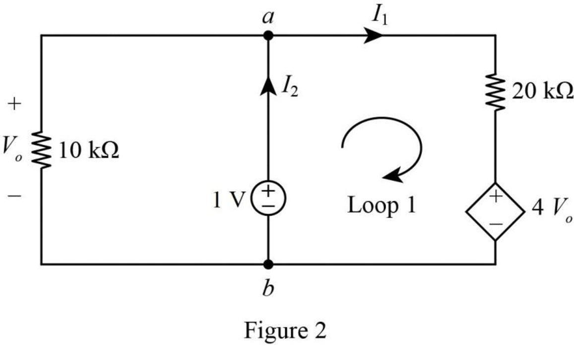
In Figure 2, apply Kirchhoff’s voltage law to the Loop 1 as follows,
In Figure 2, the voltage
Substitute
Simplify the equation as follows,
In Figure 2, the current
Substitute
Simplify the equation as follows,
In Figure 2, the Thevenin resistance is,
Substitute
Conclusion:
Thus, the Thevenin voltage is
Want to see more full solutions like this?
Chapter 4 Solutions
FUND.OF ELECTRIC CIRCUITS (LL)-W/ACCESS
Additional Engineering Textbook Solutions
ANALYSIS+DESIGN OF LINEAR CIRCUITS(LL)
Basic Engineering Circuit Analysis
Introductory Circuit Analysis (13th Edition)
Engineering Electromagnetics
Electronics Fundamentals: Circuits, Devices & Applications
Principles Of Electric Circuits


- Question: 4.12 Determine vo in the circuit of Fig. 4.80 using the superposition principle.arrow_forward4.53 Find the Norton equivalent at terminals a-b of thecircuit in Fig. 4.119.arrow_forward4.57 Obtain the Thevenin and Norton equivalent circuitsat terminals a-b for the circuit in Fig. 4.123.arrow_forward
- Using the superstition theorem, how would I prove the second images problem, given that #2 (voltage source was replaced with a short) measured 5 amps, and #4 (had the current source replaced with an open circuit) measured 1.6 amps?arrow_forwardCalculate the Thevenin equivalent circuit seen through the terminals (a, b) & draw the equivalent mThevenin equivalent.arrow_forward#7. Use Nodal analysis, Mesh Analysis, and Superposition to solve following problem: Determine v, in the circuit of Fig. 4.80]arrow_forward
- Calculate the Thevenin equivalent for the given circuit.arrow_forwardUsing Thevenin’s theorem, find the equivalent circuit to the left of the terminals in the circuit of Fig. 4.30. Then find I.arrow_forward"SUPERPOSITION THEOREM" Please Find the Vo Using SUPERPOSITION THEOREM thankyou very much! I've included a cicruit app to check if your answer was correct and close to the value of currents and voltages which is 0.5V thankyou! I've been testing simple circuits to practice problems using different theorems,I appreciate you very much Thankyou!arrow_forward
 Introductory Circuit Analysis (13th Edition)Electrical EngineeringISBN:9780133923605Author:Robert L. BoylestadPublisher:PEARSON
 Delmar's Standard Textbook Of ElectricityElectrical EngineeringISBN:9781337900348Author:Stephen L. HermanPublisher:Cengage Learning
 Programmable Logic ControllersElectrical EngineeringISBN:9780073373843Author:Frank D. PetruzellaPublisher:McGraw-Hill Education
 Fundamentals of Electric CircuitsElectrical EngineeringISBN:9780078028229Author:Charles K Alexander, Matthew SadikuPublisher:McGraw-Hill Education
 Electric Circuits. (11th Edition)Electrical EngineeringISBN:9780134746968Author:James W. Nilsson, Susan RiedelPublisher:PEARSON
 Engineering ElectromagneticsElectrical EngineeringISBN:9780078028151Author:Hayt, William H. (william Hart), Jr, BUCK, John A.Publisher:Mcgraw-hill Education,