
Concept explainers
Videos
For the circuit in Fig. 4.109, find the Thevenin equivalent between terminals a and b.
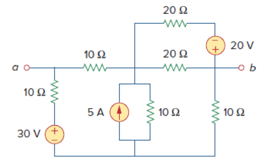
Figure 4.109
Find the Thevenin voltage and Thevenin resistance at terminals a-b of the circuit shown in Figure 4.109.
Answer to Problem 42P
The Thevenin voltage is
Explanation of Solution
Given data:
Refer to Figure 4.109 in the textbook.
The voltage source is
The current source is
Calculation:
In the given circuit, find the Thevenin resistance by turning off
The modified circuit is shown in Figure 1.
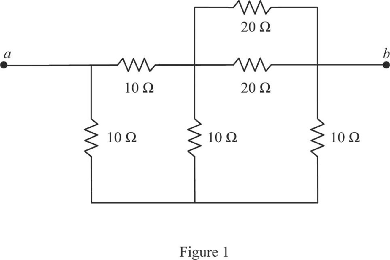
In Figure 1,
The modified circuit is shown in Figure 2.
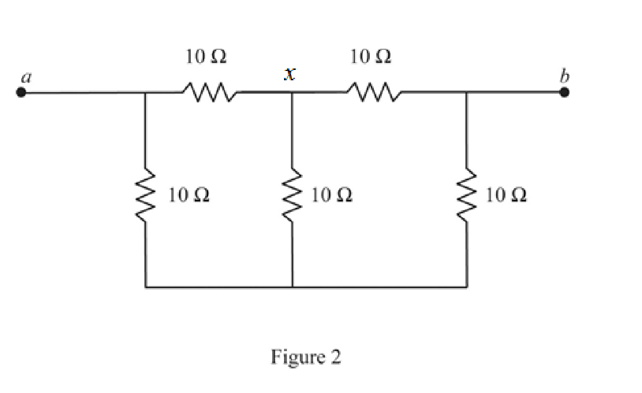
In Figure 2, the three
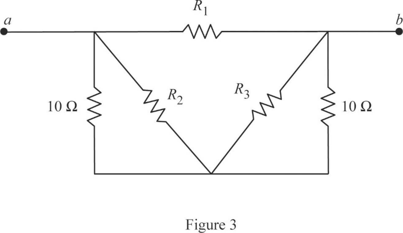
For the delta connection in Figure 3, the value of the resistor
Similarly,
And,
The modified circuit is shown in Figure 4.
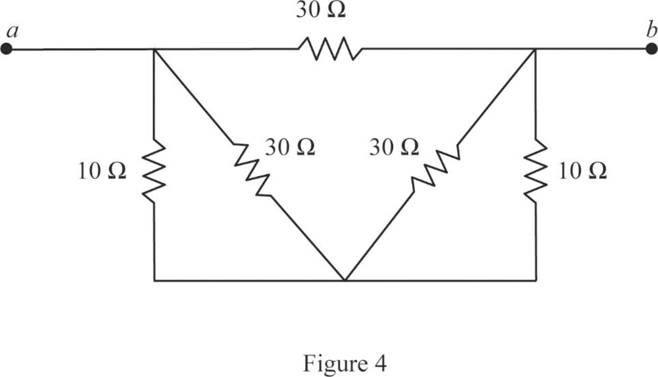
In Figure 4,
The modified circuit is shown in Figure 5.

In Figure 5, the Thevenin resistance is,
Refer to Figure 4.109 in the textbook.
The given circuit is modified as shown in Figure 6.
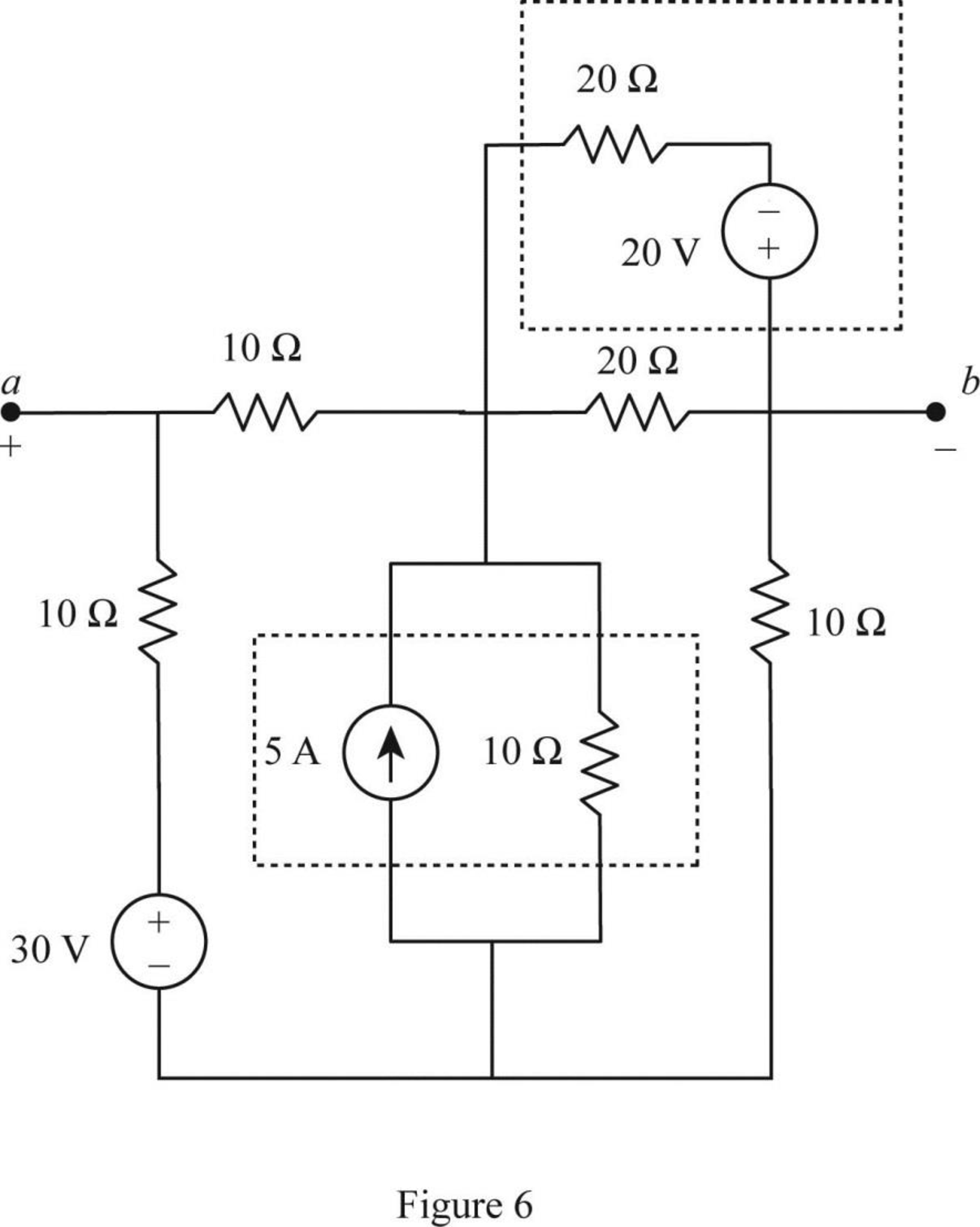
In Figure 6, the voltage source with series resistance is converted into current source with parallel resistance by source transformation method.
That is,
Similarly, the current source with parallel resistance is converted into voltage source with series resistance by source transformation method.
That is,
The source transformation is shown in Figure 7.
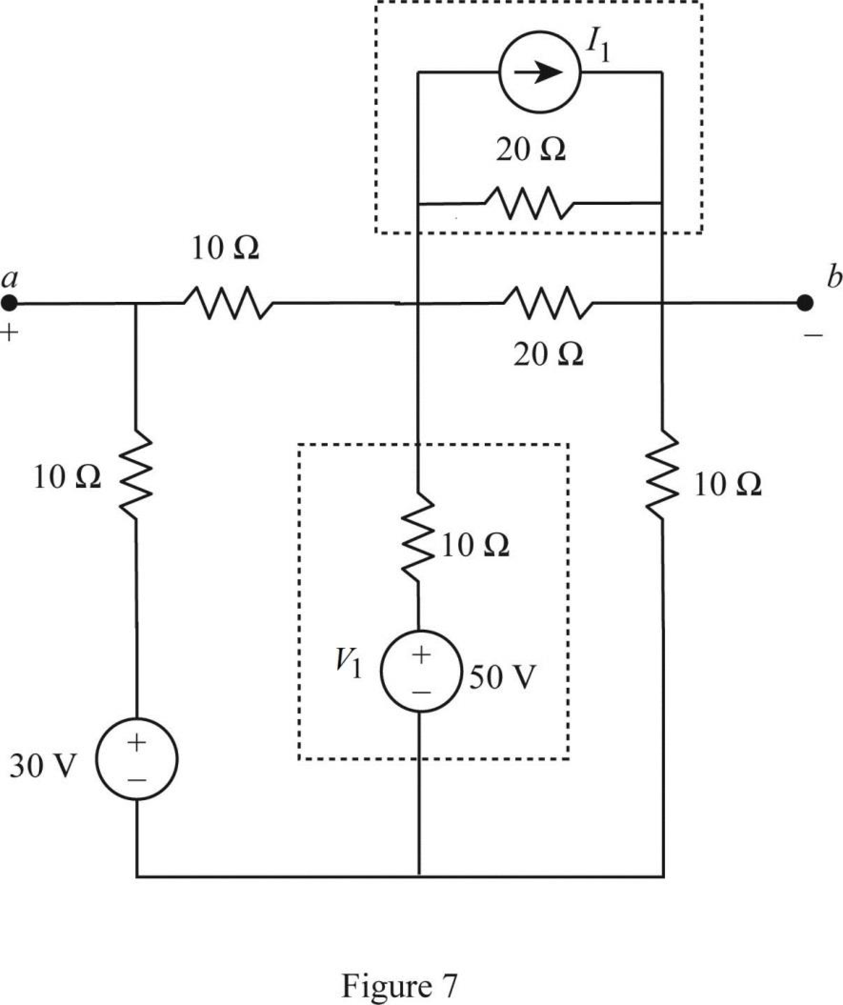
In Figure 7,
The modified circuit is shown in Figure 8.
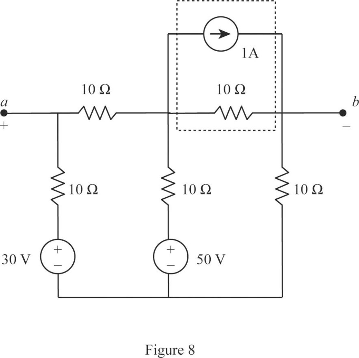
In Figure 8, the current source with parallel resistance is converted into voltage source with series resistance by source transformation method.
That is,
The source transformation is shown in Figure 9.
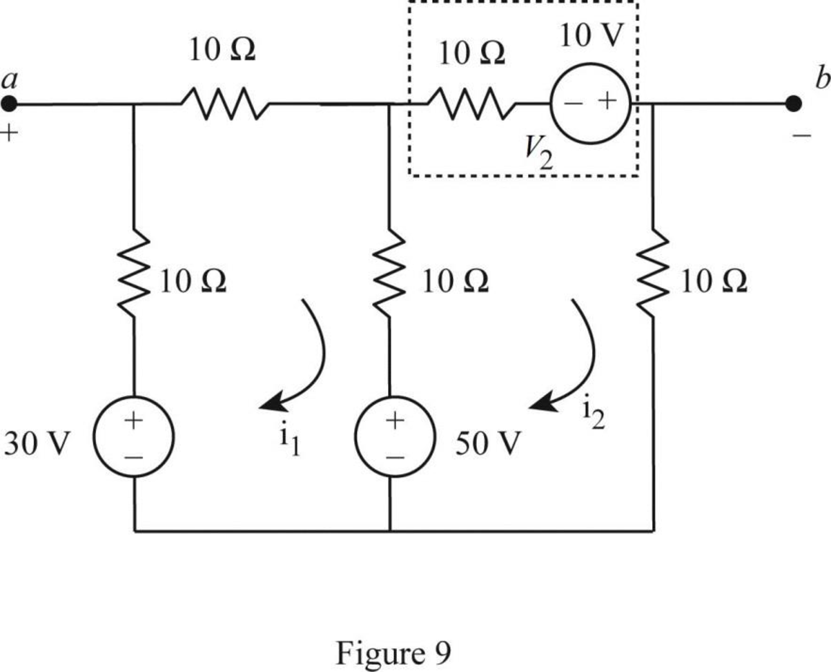
In Figure 9, apply Kirchhoff’s voltage law to the loop
Rearrange the equation (1) as follows,
In Figure 9, apply Kirchhoff’s voltage law to the loop
Substitute
Substitute 0 for
In Figure 9, apply Kirchhoff’s voltage law to the outer loop as follows.
Substitute 0 for
Since, the voltage
The Thevenin equivalent is shown in Figure 10.
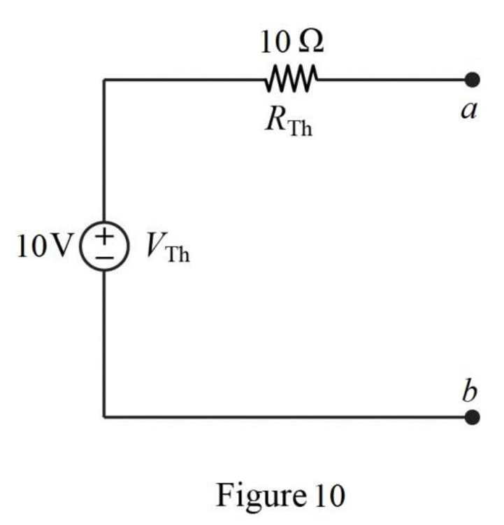
Conclusion:
Thus, the Thevenin voltage is
Want to see more full solutions like this?
Chapter 4 Solutions
Fundamentals Of Electric Circuits + 1 Semester Connect Access Card
Additional Engineering Textbook Solutions
Introductory Circuit Analysis (13th Edition)
Programmable Logic Controllers
ANALYSIS+DESIGN OF LINEAR CIRCUITS(LL)
Loose Leaf for Engineering Circuit Analysis Format: Loose-leaf
Electrical Engineering: Principles & Applications (7th Edition)
Engineering Electromagnetics


- Use superposition to find v0 in the circuit of Fig.4.77.arrow_forward#7. Use Nodal analysis, Mesh Analysis, and Superposition to solve following problem: Determine v, in the circuit of Fig. 4.80]arrow_forwardQuestion: 4.12 Determine vo in the circuit of Fig. 4.80 using the superposition principle.arrow_forward
- Find the Thevenin equivalent circuit of the circuit in Fig. 4.34 to the left of the terminals.arrow_forwardNumber 4.29 Use source transformation to find correctly Vo in the circuit of Fig. 4.97.arrow_forwardUsing Thevenin’s theorem, find the equivalent circuit to the left of the terminals in the circuit of Fig. 4.30. Then find I.arrow_forward
- Using the superstition theorem, how would I prove the second images problem, given that #2 (voltage source was replaced with a short) measured 5 amps, and #4 (had the current source replaced with an open circuit) measured 1.6 amps?arrow_forward4) Draw the Norton Equivalent of the circuit below.arrow_forwardCalculate the Thevenin equivalent circuit seen through the terminals (a, b) & draw the equivalent mThevenin equivalent.arrow_forward
- 4.70 Determine the maximum power delivered to the variable resistor R shown in the circuit of Fig. 4.136.arrow_forward4.48 Determine the Norton equivalent at terminals a-b forthe circuit in Fig. 4.115.arrow_forwardUsing, necessarily, the superposition method, calculate the voltage that is applied on the terminals of the current source.arrow_forward
 Introductory Circuit Analysis (13th Edition)Electrical EngineeringISBN:9780133923605Author:Robert L. BoylestadPublisher:PEARSON
 Delmar's Standard Textbook Of ElectricityElectrical EngineeringISBN:9781337900348Author:Stephen L. HermanPublisher:Cengage Learning
 Programmable Logic ControllersElectrical EngineeringISBN:9780073373843Author:Frank D. PetruzellaPublisher:McGraw-Hill Education
 Fundamentals of Electric CircuitsElectrical EngineeringISBN:9780078028229Author:Charles K Alexander, Matthew SadikuPublisher:McGraw-Hill Education
 Electric Circuits. (11th Edition)Electrical EngineeringISBN:9780134746968Author:James W. Nilsson, Susan RiedelPublisher:PEARSON
 Engineering ElectromagneticsElectrical EngineeringISBN:9780078028151Author:Hayt, William H. (william Hart), Jr, BUCK, John A.Publisher:Mcgraw-hill Education,