Concept explainers
Videos
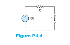
In the circuit shown in Figure P4.4, assume
Find:
a. The energy stored in the inductor for all time.
b. The energy delivered by the source for all time.
(a)
The energy stored in the inductor.
Answer to Problem 4.6HP
The energy stored in the inductor for different time interval is
Explanation of Solution
Calculation:
The given diagram is shown in Figure 1
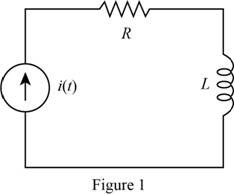
The expression for the energy stored in the conductor is given by,
Substitute
Substitute
Substitute
Substitute
The expression for the energy stored in the inductor for different time interval is given by,
Conclusion:
Therefore, the energy stored in the inductor for different time interval is
(b)
Theenergy delivered by the source.
Answer to Problem 4.6HP
The energy delivered by the source for various time interval is
Explanation of Solution
Calculation:
The expression for the energy stored in the conductor is given by,
Substitute,
Substitute,
The energy dissipated by the resistor from
Substitute
Solve further as,
Substitute
The expression for the power delivered by the source for
Substitute
The expression for the energy dissipated in the resistor from
Substitute
The expression for the energy delivered by the source for the time
Substitute
The energy delivered by the source for various time interval is given by,
Conclusion:
Therefore, the energy delivered by the source for various time interval is
Want to see more full solutions like this?
Chapter 4 Solutions
Loose Leaf For Principles And Applications Of Electrical Engineering


- The circuit shown in Figure P4.39 is operating in steady state with the switch closed prior to t=0. Find expressions for i L ( t ) for t<0 and for t≥0. Sketch iL(t) to scale versus timearrow_forwardi find in other explain to this that the answer is Vc+4i(x). ,,,,, but why it's not VL + Vc + 4i(x) explain the answer pleasearrow_forwardA dc source is connected to a series RLC circuit by a switch that closes at t=0, as shownin Figure P4.61. The initial conditions are i(0+)=0 and vC(0+)=0. Write the differentialequation for vC(t).Solve for v C ( t ), if R = 20 Ω.arrow_forward
- Determine expressions for and sketch v R ( t ) to scale versus time for the circuit of Figure P4.43. The circuit is operating in steady state with the switch closed prior to t=0. Consider the time interval −1≤t≤5 ms.arrow_forwardDetermine expressions for and sketch is(t) toscale versus time for -0.2 … t … 1.0 s for thecircuit of Figure P4.37 using a differential equation.arrow_forwardConsider the circuit shown in Figure T4.3.a. Write the differential equation for i(t). b. Find the time constant and the form of the complementary solution. c. Find the particular solution. d. Find the complete solution for i(t).arrow_forward
- Consider the circuit shown in Figure P4.55. a. Write the differential equation for v(t).b. Find the time constant and the form of the complementary solution.c. Usually, for an exponential forcing function like this, we would try a particular solution ofthe form vp(t) = K exp (−10t). Why doesn’t that work in this case?d. Find the particular solution. [Hint: Try a particular solution of the form vp(t)=K t exp (−10t). How ]e. Find the complete solution for v(t).arrow_forwardSolve for i L ( t ) for t>0 in the circuit of Figure P4.48. You will need to make an educated guess as to the form of the particular solution. [Hint: The particular solution includes terms with the same functional forms as the terms found in the forcing function and its derivatives.]arrow_forwardConsider the circuit shown in Figure P4.54. a. Write the differential equation for i(t). b. Find the time constant and the form of the complementary solution. c. Usually, for an exponential forcing function like this, we would try a particular solution of the form ip(t)=K exp (−3t). Why doesn’t that work in this case? d. Find the particular solution. [Hint: Try a particular solution of the form ip(t)=K t exp(−3t).] e. Find the complete solution for i(t).arrow_forward
- The switch shown in Figure P4.42 has been closed for a long time prior to t=0, then it opens at t=0 and closes again at t=1s. Find i L (t) for all t.arrow_forwardConsider the circuit shown in Figure P4.70. a. Write the differential equation for v(t). b. Find the damping coefficient, the natural frequency, and the form of the complementary solution. c. Usually, for a sinusoidal forcing function, we try a particular solution of the form v p ( t)=A cos( 10 4 t )+B sin( 10 4 t ). Why doesn’t that work in this case? d. Find the particular solution. [Hint: Try a particular solution of the form v p ( t)=At cos( 10 4 t )+B t sin( 10 4 t ). ] e. Find the complete solution for v(t).arrow_forwardWrite the differential equation for i L(t) and find the complete solution for the circuit of Figure P4.45. [Hint: Try a particular solution of the form i Lp ( t )=A e −t .]arrow_forward
 Introductory Circuit Analysis (13th Edition)Electrical EngineeringISBN:9780133923605Author:Robert L. BoylestadPublisher:PEARSON
 Delmar's Standard Textbook Of ElectricityElectrical EngineeringISBN:9781337900348Author:Stephen L. HermanPublisher:Cengage Learning
 Programmable Logic ControllersElectrical EngineeringISBN:9780073373843Author:Frank D. PetruzellaPublisher:McGraw-Hill Education
 Fundamentals of Electric CircuitsElectrical EngineeringISBN:9780078028229Author:Charles K Alexander, Matthew SadikuPublisher:McGraw-Hill Education
 Electric Circuits. (11th Edition)Electrical EngineeringISBN:9780134746968Author:James W. Nilsson, Susan RiedelPublisher:PEARSON
 Engineering ElectromagneticsElectrical EngineeringISBN:9780078028151Author:Hayt, William H. (william Hart), Jr, BUCK, John A.Publisher:Mcgraw-hill Education,