Fundamentals of Electric Circuits
6th Edition
ISBN: 9780078028229
Author: Charles K Alexander, Matthew Sadiku
Publisher: McGraw-Hill Education
bartleby

Concept explainers

bartleby

Videos

Textbook Question
Book Icon
Chapter 4, Problem 68P

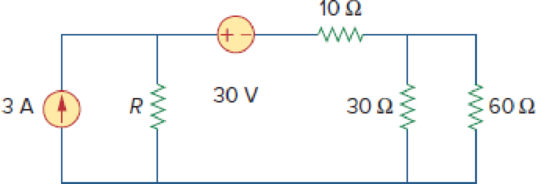
Consider the 30-Ω resistor in Fig. 4.134. First compute the Thevenin equivalent circuit as seen by the 30-Ω resistor. Compute the value of R that results in Thevenin equivalent resistance equal to the 30-Ω resistance and then calculate power delivered to the 30-Ω resistor. Now let R = 0 Ω, 110 Ω, and ∞, calculate the power delivered to the 30-Ω resistor in each case. What can you say about the value of R that will result in the maximum power that can be delivered to the 30-Ω resistor?

Figure 4.134

Chapter 4, Problem 68P, Consider the 30- resistor in Fig. 4.134. First compute the Thevenin equivalent circuit as seen by

Expert Solution & Answer
Check Mark
To determine

Find the Thevenin equivalent seen by the 30Ω resistor of the circuit shown in Figure 4.134 and find the value of R in the circuit.

Calculate the power delivered to the 30Ω resistor when R=0Ω, 100Ω, and . Examine about the value of R that result in delivering maximum power to the 30Ω resistor.

Answer to Problem 68P

The Thevenin voltage is 60V, the Thevenin resistance is 30Ω, and the value of R is 50Ω for the given circuit.

The power delivered to the 30Ω resistor when R=0Ω, R=100Ω, and R= is 13.329W, 61.22W, and 120W respectively. The maximum power will be delivered to the 30Ω resistor must be when R=.

Explanation of Solution

Given data:

Refer to Figure 4.134 in the textbook.

The current source is 3A.

The voltage source is 30V.

The Thevenin resistance RTh is 30Ω.

Calculation:

In the given circuit, find the Thevenin voltage by removing the 30 ohms resistor and the modified circuit is shown in Figure 1.

The modified circuit is shown in Figure 1.

Fundamentals of Electric Circuits, Chapter 4, Problem 68P , additional homework tip  1

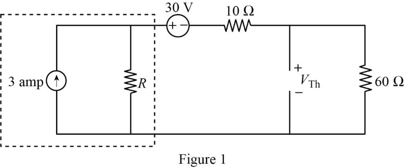
In Figure 1, the current source with parallel resistance is converted into voltage source with series resistance using source transformation. The voltage V is calculated by using ohms law as follows,

V=3R

The source transformation is shown in Figure 2.

Fundamentals of Electric Circuits, Chapter 4, Problem 68P , additional homework tip  2

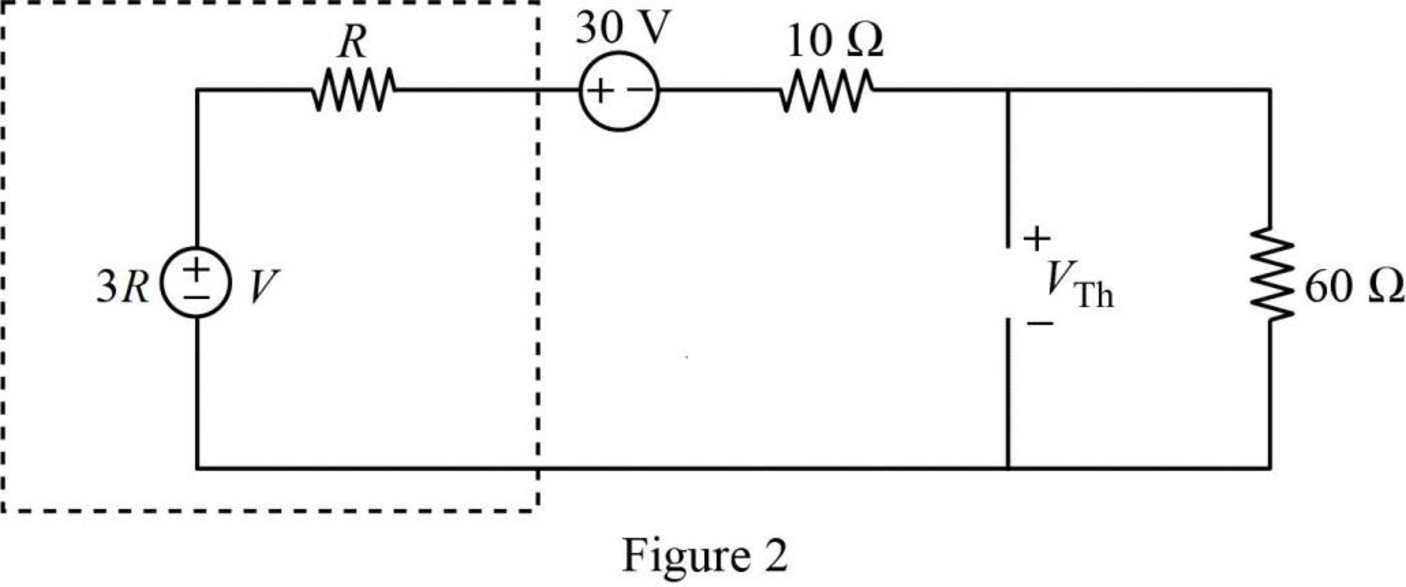
In Figure 2, the Thevenin voltage is,

VTh=60[(3R30)(R+10+60)]        (1)

Refer to Figure 4.134 in the textbook.

In the given circuit, find the Thevenin resistance by turning off the 30V voltage (replace with a short circuit) and 3A current source (replace with an open circuit).

The modified circuit is shown in Figure 3.

Fundamentals of Electric Circuits, Chapter 4, Problem 68P , additional homework tip  3

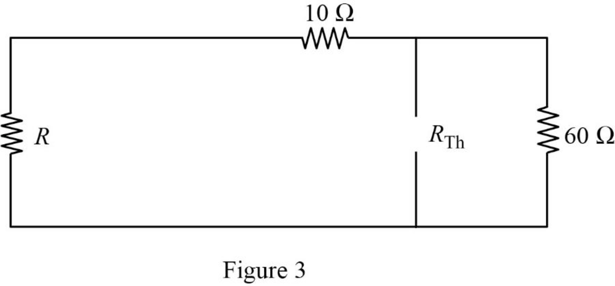
In Figure 3, the Thevenin resistance is,

RTh=60||(R+10)

RTh=60(R+10)R+60+10        (2)

Substitute 30 for RTh in equation (2) to find the value of the resistor R in ohms.

30=60(R+10)(R+60+10)30(R+60+10)=60(R+10)30R+1800+300=60R+600R=50Ω

Substitute 50 for R in equation (1) to find the Thevenin voltage in volts.

VTh=60[(3(50)30)(50+10+60)]=60×120120=60V

Substitute 50 for R in equation (2) to find the Thevenin resistance in ohms.

RTh=60(50+10)50+60+10=30Ω

The Thevenin equivalent connected to the 30 ohms resistor is shown in Figure 4.

Fundamentals of Electric Circuits, Chapter 4, Problem 68P , additional homework tip  4

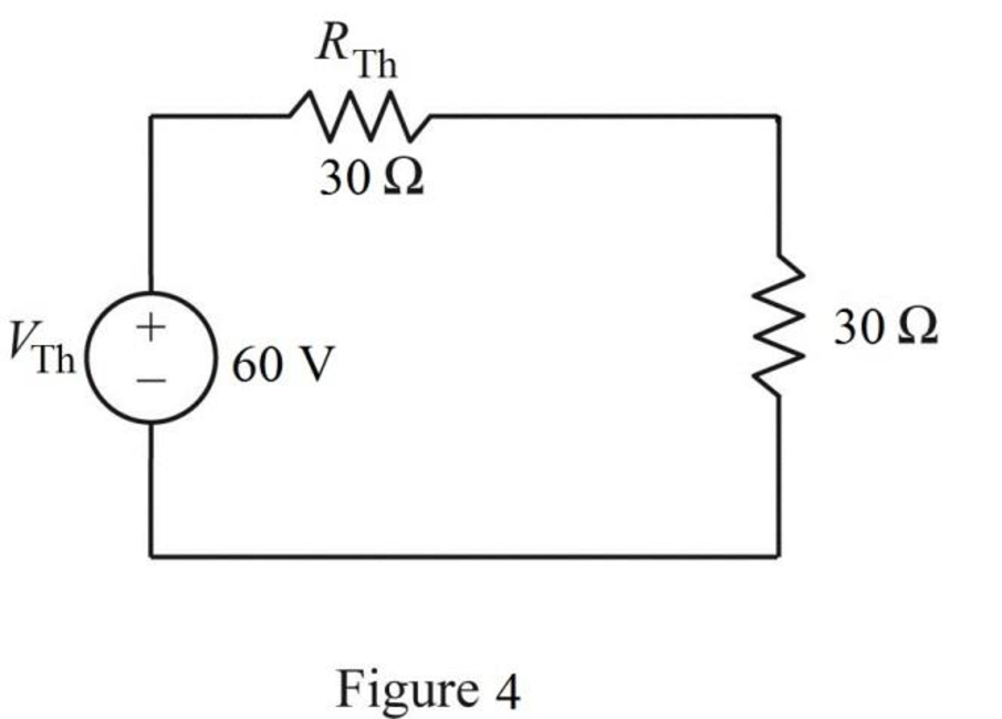
The power delivered to the 30 ohms resistor is,

p30Ω=[VThRTh+30]2(30)        (3)

Substitute 60 for VTh and 30 for RTh in equation (3) to find the power delivered to the 30 ohms resistor in watts.

p30Ω=[6030+30]2(30)=30W

Consider the resistance R=0Ω.

When R=0Ω, the Thevenin resistance is calculated as follows.

Substitute 0 for R in equation (2) to find the Thevenin resistance in ohms.

RTh=60(0+10)0+60+10=8.571Ω

When R=0Ω, the Thevenin voltage is calculated as follows.

Substitute 0 for R in equation (1) to find the Thevenin voltage in volts.

VTh=60[(3(0)30)(0+10+60)]=25.71V

When R=0Ω, the power delivered to the 30 ohms resistor is calculated as follows.

Substitute 25.71 for VTh and 8.571 for RTh in equation (3) to find the power delivered to the 30 ohms resistor in watts.

p30Ω=[25.718.571+30]2(30)=13.329W

Consider the resistance R=110Ω.

When R=110Ω, the Thevenin resistance is calculated as follows.

Substitute 110 for R in equation (2) to find the Thevenin resistance in ohms.

RTh=60(110+10)110+60+10=40Ω

When R=110Ω, the Thevenin voltage is calculated as follows.

Substitute 110 for R in equation (1) to find the Thevenin voltage in volts.

VTh=60[(3(110)30)(110+10+60)]=100V

When R=110Ω, the power delivered to the 30 ohms resistor is calculated as follows.

Substitute 100 for VTh and 40 for RTh in equation (3) to find the power delivered to the 30 ohms resistor in watts.

p30Ω=[10040+30]2(30)=61.22W

Consider the resistance R=.

When R=, the Thevenin resistance is calculated as follows.

Simplify equation (2) as follows,

RTh=60R(1+10R)R(1+60R+10R)=60(1+10R)1+60R+10R

Substitute for R in to find the Thevenin resistance in ohms.

RTh=60(1+10)1+60+10=60(1+0)1+0+0{1=0}=60Ω

When R=, the Thevenin voltage is calculated as follows.

Simplify equation (1) as follows,

VTh=60[(3R30)(R+10+60)]=60[R(330R)R(1+10R+60R)]=60[330R1+10R+60R]

Substitute for R to find the Thevenin voltage in volts.

VTh=60[3301+10+60]=60[301+0+0]{1=0}=180V

When R=, the power delivered to the 30 ohms resistor is calculated as follows.

Substitute 180 for VTh and 60 for RTh in equation (3) to find the power delivered to the 30 ohms resistor in watts.

p30Ω=[18060+30]2(30)=120W

Thus, when R=, the maximum power will be delivered to the 30 ohms resistor.

Conclusion:

Thus, the Thevenin voltage is 60V, the Thevenin resistance is 30Ω, and the value of R is 50Ω for the given circuit.

The power delivered to the 30Ω resistor when R=0Ω, R=100Ω, and R= is 13.329W, 61.22W, and 120W respectively. The maximum power will be delivered to the 30Ω resistor must be when R=.

Want to see more full solutions like this?

Subscribe now to access step-by-step solutions to millions of textbook problems written by subject matter experts!
Students have asked these similar questions
Find the Norton equivalent for the circuit in Fig. 4.129
4.53 Find the Norton equivalent at terminals a-b of thecircuit in Fig. 4.119.
4) Draw the Norton Equivalent of the circuit below.

Chapter 4 Solutions

Fundamentals of Electric Circuits

Ch. 4.6 - Find the Norton equivalent circuit for the circuit...Ch. 4.6 - Find the Norton equivalent circuit of the circuit...Ch. 4.8 - Determine the value of RL that will draw the...Ch. 4.9 - Rework Practice Prob. 4.9 using PSpice. Find the...Ch. 4.9 - Fin d the maximum power transferred to RL if the...Ch. 4.10 - The measured open-circuit voltage across a certain...Ch. 4.10 - Prob. 17PPCh. 4.10 - Obtain the current through the galvanometer,...Ch. 4 - The current through a branch in a linear network...Ch. 4 - For superposition, it is not required that only...Ch. 4 - The superposition principle applies to power...Ch. 4 - Refer to Fig. 4.67. The Thevenin resistance at...Ch. 4 - The Thevenin voltage across terminals a and b of...Ch. 4 - The Norton current at terminals a and b of the...Ch. 4 - The Norton resistance RN is exactly equal to the...Ch. 4 - Which pair of circuits in Fig. 4.68 are...Ch. 4 - A load is connected to a network. At the terminals...Ch. 4 - The source is supplying the maximum power to the...Ch. 4 - Calculate the current io in the circuit of Fig....Ch. 4 - Using Fig. 4.70, design a problem to help other...Ch. 4 - (a) In the circuit of Fig. 4.71, calculate vo and...Ch. 4 - Use linearity to determine io in the circuit of...Ch. 4 - For the circuit in Fig. 4.73, assume vo = 1 V, and...Ch. 4 - For the linear circuit shown in Fig. 4.74, use...Ch. 4 - Use linearity and the assumption that Vo = 1 V to...Ch. 4 - Using superposition, find Vo in the circuit of...Ch. 4 - Given that I = 6 amps when Vs = 160 volts and Is =...Ch. 4 - Using Fig. 4.78, design a problem to help other...Ch. 4 - Use the superposition principle to find io and vo...Ch. 4 - Determine vo in the circuit of Fig. 4.80 using the...Ch. 4 - Use superposition to find vo in the circuit of...Ch. 4 - Apply the superposition principle to find vo in...Ch. 4 - For the circuit in Fig. 4.83, use superposition to...Ch. 4 - Given the circuit in Fig. 4.84, use superposition...Ch. 4 - Use superposition to obtain vx in the circuit of...Ch. 4 - Use superposition to find Vo in the circuit of...Ch. 4 - Use superposition to solve for vx in the circuit...Ch. 4 - Use source transformation to reduce the circuit...Ch. 4 - Using Fig. 4.89, design a problem to help other...Ch. 4 - For the circuit in Fig, 4.90, use source...Ch. 4 - Referring to Fig. 4.91, use source transformation...Ch. 4 - Use source transformation to find the voltage Vx...Ch. 4 - Obtain vo in the circuit of Fig. 4.93 using source...Ch. 4 - Use source transformation to find io in the...Ch. 4 - Apply source transformation to find vx in the...Ch. 4 - Use source transformation to find Io in Fig. 4.96....Ch. 4 - Use source transformation to find vo in the...Ch. 4 - Use source transformation on the circuit shown in...Ch. 4 - Determine vx in the circuit of Fig. 4.99 using...Ch. 4 - Use source transformation to find ix in the...Ch. 4 - Determine the Thevenin equivalent circuit, shown...Ch. 4 - Using Fig. 4.102, design a problem that will help...Ch. 4 - Use Thevenins theorem to find vo in Prob. 4.12....Ch. 4 - Solve for the current i in the circuit of Fig....Ch. 4 - Find the Norton equivalent with respect to...Ch. 4 - Apply Thevenins theorem to find Vo in the circuit...Ch. 4 - Obtain the Thevenin equivalent at terminals a-b of...Ch. 4 - Find the Thevenin equivalent at terminals a-b of...Ch. 4 - Find the Thevenin and Norton equivalents at...Ch. 4 - For the circuit in Fig. 4.109, find the Thevenin...Ch. 4 - Find the Thevenin equivalent looking into...Ch. 4 - For the circuit in Fig. 4.111, obtain the Thevenin...Ch. 4 - Find the Thevenin equivalent of the circuit in...Ch. 4 - Using Fig. 4.113, design a problem to help other...Ch. 4 - Obtain the Thevenin and Norton equivalent circuits...Ch. 4 - Determine the Norton equivalent at terminals a-b...Ch. 4 - Find the Norton equivalent looking into terminals...Ch. 4 - Obtain the Norton equivalent of the circuit in...Ch. 4 - Given the circuit in Fig. 4.117, obtain the Norton...Ch. 4 - For the transistor model in Fig. 4.118, obtain the...Ch. 4 - Find the Norton equivalent at terminals a-b of the...Ch. 4 - Find the Thevenin equivalent between terminals a-b...Ch. 4 - Obtain the Norton equivalent at terminals a-b of...Ch. 4 - Use Nortons theorem to find Vo in the circuit of...Ch. 4 - Obtain the Thevenin and Norton equivalent circuits...Ch. 4 - The network in Fig. 4.124 models a bipolar...Ch. 4 - Determine the Thevenin and Norton equivalents at...Ch. 4 - For the circuit in Fig. 4.126, find the Thevenin...Ch. 4 - Obtain the Thevenin and Norton equivalent circuits...Ch. 4 - Find the Thevenin equivalent of the circuit in...Ch. 4 - Find the Norton equivalent for the circuit in Fig....Ch. 4 - Obtain the Thevenin equivalent seen at terminals...Ch. 4 - For the circuit shown in Fig. 4.131, determine the...Ch. 4 - Find the maximum power that can be delivered to...Ch. 4 - The variable resistor R in Fig. 4.133 is adjusted...Ch. 4 - Consider the 30- resistor in Fig. 4.134. First...Ch. 4 - Find the maximum power transferred to resistor R...Ch. 4 - Determine the maximum power delivered to the...Ch. 4 - For the circuit in Fig. 4.137, what resistor...Ch. 4 - (a) For the circuit in Fig. 4.138, obtain the...Ch. 4 - Determine the maximum power that can be delivered...Ch. 4 - For the bridge circuit shown in Fig. 4.140, find...Ch. 4 - For the circuit in Fig. 4.141, determine the value...Ch. 4 - Solve Prob. 4.34 using PSpice or MultiSim. Let V =...Ch. 4 - Use PSpice or MultiSim to solve Prob. 4.44. For...Ch. 4 - Use PSpice or MultiSim to solve Prob. 4.52.Ch. 4 - Obtain the Thevenin equivalent of the circuit in...Ch. 4 - Use PSpice or MultiSim to find the Thevenin...Ch. 4 - For the circuit in Fig. 4.126, use PSpice or...Ch. 4 - An automobile battery has an open circuit voltage...Ch. 4 - The following results were obtained from...Ch. 4 - When connected to a 4- resistor, a battery has a...Ch. 4 - The Thevenin equivalent at terminals a-b of the...Ch. 4 - A black box with a circuit in it is connected to a...Ch. 4 - A transducer is modeled with a current source Is...Ch. 4 - Consider the circuit in Fig. 4.144. An ammeter...Ch. 4 - Consider the circuit in Fig. 4.145. (a) Replace...Ch. 4 - The Wheatstone bridge circuit shown in Fig. 4.146...Ch. 4 - (a) In the Wheatstone bridge circuit of Fig. 4.147...Ch. 4 - Consider the bridge circuit of Fig. 4.148. Is the...Ch. 4 - The circuit in Fig. 4.149 models a common-emitter...Ch. 4 - An attenuator is an interface circuit that reduces...Ch. 4 - A dc voltmeter with a sensitivity of 10 k/V is...Ch. 4 - A resistance array is connected to a load resistor...Ch. 4 - A common-emitter amplifier circuit is shown in...Ch. 4 - For Practice Prob. 4.18, determine the current...
Knowledge Booster
Background pattern image
Electrical Engineering
Learn more about
Need a deep-dive on the concept behind this application? Look no further. Learn more about this topic, electrical-engineering and related others by exploring similar questions and additional content below.
Similar questions
SEE MORE QUESTIONS
Recommended textbooks for you
Text book image
Introductory Circuit Analysis (13th Edition)
Electrical Engineering
ISBN:9780133923605
Author:Robert L. Boylestad
Publisher:PEARSON
Text book image
Delmar's Standard Textbook Of Electricity
Electrical Engineering
ISBN:9781337900348
Author:Stephen L. Herman
Publisher:Cengage Learning
Text book image
Programmable Logic Controllers
Electrical Engineering
ISBN:9780073373843
Author:Frank D. Petruzella
Publisher:McGraw-Hill Education
Text book image
Fundamentals of Electric Circuits
Electrical Engineering
ISBN:9780078028229
Author:Charles K Alexander, Matthew Sadiku
Publisher:McGraw-Hill Education
Text book image
Electric Circuits. (11th Edition)
Electrical Engineering
ISBN:9780134746968
Author:James W. Nilsson, Susan Riedel
Publisher:PEARSON
Text book image
Engineering Electromagnetics
Electrical Engineering
ISBN:9780078028151
Author:Hayt, William H. (william Hart), Jr, BUCK, John A.
Publisher:Mcgraw-hill Education,
Norton's Theorem and Thevenin's Theorem - Electrical Circuit Analysis; Author: The Organic Chemistry Tutor;https://www.youtube.com/watch?v=-kkvqr1wSwA;License: Standard Youtube License