
Concept explainers
Videos
Find the maximum power transferred to resistor R in the circuit of Fig. 4.135.
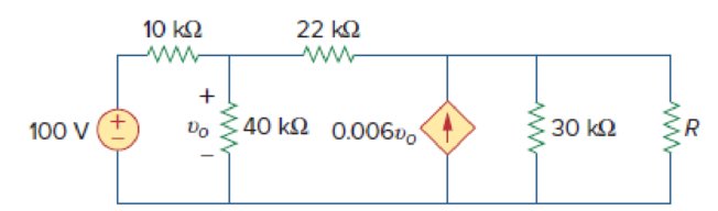
Figure 4.135
Calculate the maximum power delivered to the resistor R of the circuit shown in Figure 4.135.
Answer to Problem 69P
The maximum power delivered to the variable resistor R is infinity.
Explanation of Solution
Given data:
Refer to Figure 4.135 in the textbook.
The voltage source is 100 V.
Formula used:
Write the expression to find the power delivered to the resistor.
Here,
Calculation:
The given circuit is modified as shown in Figure 1.
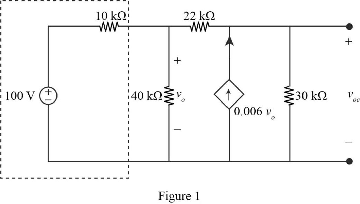
In Figure 1, the voltage source with series resistance is converted into current source with parallel resistance using source transformation. The current (I) is calculated by using Ohm’s law.
The source transformation is shown in Figure 2.
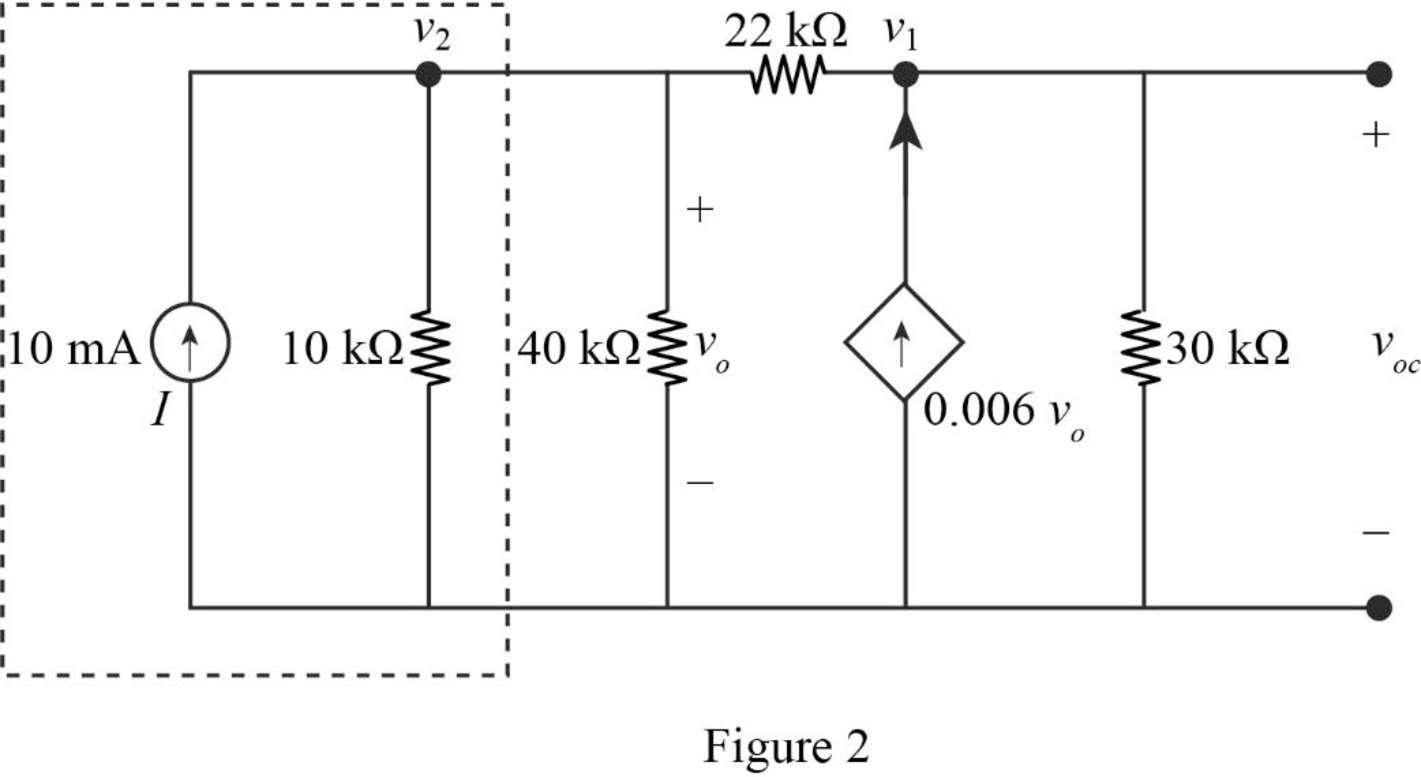
In Figure 2, apply Kirchhoff’s current law at node voltage
Simplify the equation as follows,
In Figure 2, apply Kirchhoff’s current law at node voltage
Substitute
Simplify the equation as follows,
Substitute
Since, the voltage at node
Refer to Figure 4.135 in the textbook.
In the given circuit, find the short circuit current by shorting the resistor R.
The modified circuit is shown in Figure 3.
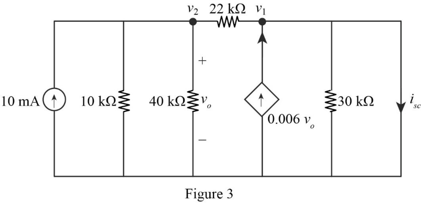
To find the short circuit current
Substitute 0 for
In Figure 3, apply Kirchhoff’s current law at node voltage
Substitute 0 for
The Thevenin resistance is,
Substitute
The negative equivalent resistance indicates that an active device (dependent source) presents in the circuit, since the circuit cannot have a negative resistance in a purely passive circuit. The negative resistance for the equivalent circuit means that both the resistance and the source will effectively delivers the power to load.
Since the resistance cannot be the negative, the correct answer will be
Conclusion:
Thus, the maximum power delivered to the variable resistor R is infinity.
Want to see more full solutions like this?
Chapter 4 Solutions
Package: Fundamentals Of Electric Circuits With 2 Semester Connect Access Card


- 4.57 Obtain the Thevenin and Norton equivalent circuitsat terminals a-b for the circuit in Fig. 4.123.arrow_forwardUse superposition to find v0 in the circuit of Fig.4.77.arrow_forward#7. Use Nodal analysis, Mesh Analysis, and Superposition to solve following problem: Determine v, in the circuit of Fig. 4.80]arrow_forward
- Given the circuit in Fig. 4.117, obtain the Norton equivalent as viewed from terminals:arrow_forwardNumber 4.29 Use source transformation to find correctly Vo in the circuit of Fig. 4.97.arrow_forwardUsing Thevenin’s theorem, find the equivalent circuit to the left of the terminals in the circuit of Fig. 4.30. Then find I.arrow_forward
- Find the Thevenin equivalent circuit of the circuit in Fig. 4.34 to the left of the terminals.arrow_forwardUsing the superstition theorem, how would I prove the second images problem, given that #2 (voltage source was replaced with a short) measured 5 amps, and #4 (had the current source replaced with an open circuit) measured 1.6 amps?arrow_forward4.70 Determine the maximum power delivered to the variable resistor R shown in the circuit of Fig. 4.136.arrow_forward
- 4.48 Determine the Norton equivalent at terminals a-b forthe circuit in Fig. 4.115.arrow_forwardA black box with a circuit in it is connected to a variable resistor. An ideal ammeter (with zero resistance) and an ideal voltmeter (with infinite resistance) are used to measure current and voltage as shown in Fig. 4.143.arrow_forwardTeaching values through exhortation can be done with the help of ____________ a. Friends b. Computers c. Neighbors d. Stories with moral lessonsarrow_forward
 Introductory Circuit Analysis (13th Edition)Electrical EngineeringISBN:9780133923605Author:Robert L. BoylestadPublisher:PEARSON
 Delmar's Standard Textbook Of ElectricityElectrical EngineeringISBN:9781337900348Author:Stephen L. HermanPublisher:Cengage Learning
 Programmable Logic ControllersElectrical EngineeringISBN:9780073373843Author:Frank D. PetruzellaPublisher:McGraw-Hill Education
 Fundamentals of Electric CircuitsElectrical EngineeringISBN:9780078028229Author:Charles K Alexander, Matthew SadikuPublisher:McGraw-Hill Education
 Electric Circuits. (11th Edition)Electrical EngineeringISBN:9780134746968Author:James W. Nilsson, Susan RiedelPublisher:PEARSON
 Engineering ElectromagneticsElectrical EngineeringISBN:9780078028151Author:Hayt, William H. (william Hart), Jr, BUCK, John A.Publisher:Mcgraw-hill Education,