
Concept explainers
Videos
For the bridge circuit shown in Fig. 4.140, find the load RL for maximum power transfer and the maximum power absorbed by the load.
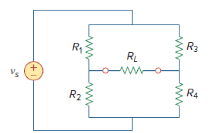
Figure 4.140
Find the maximum power transferred and maximum power absorbed by the load resistor
Answer to Problem 74P
The maximum power transferred and maximum power absorbed by the load resistor
Explanation of Solution
Given data:
Refer to Figure 4.140 in the textbook.
The voltage source is
Formula used:
Write the expression to find the power delivered to the resistor.
Here,
Calculation:
In the given circuit, find the Thevenin resistance by turning off the voltage source
The modified circuit is shown in Figure 1.
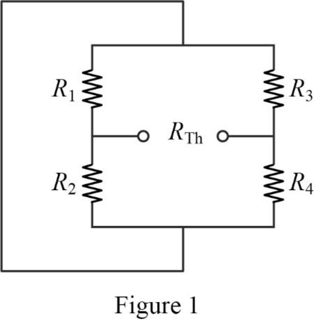
In Figure 1, the Thevenin resistance is,
Refer to Figure 4.139 in the textbook.
The given circuit is modified as shown in Figure 2 to find the Thevenin voltage.
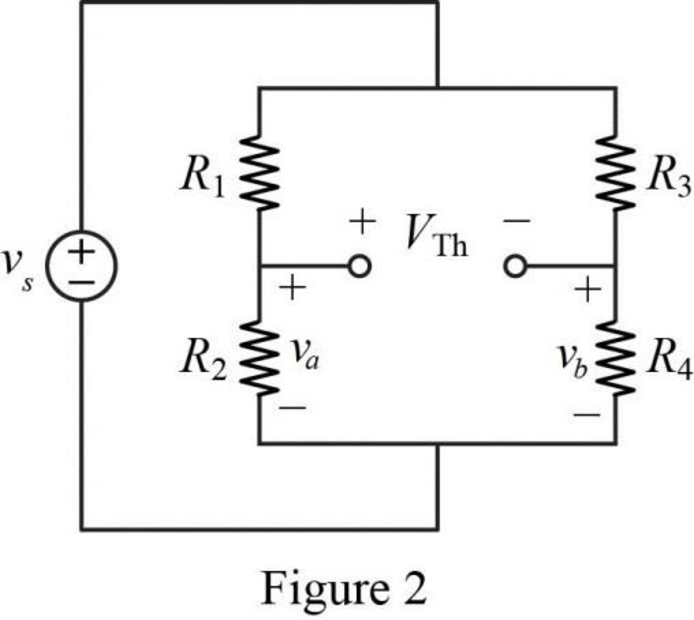
In Figure 2, the voltage
In Figure 2, the voltage
In Figure 2, apply Kirchhoff’s voltage law for the right bottom loop as follows.
Substitute
Substitute
Conclusion:
Thus, the maximum power transferred and maximum power absorbed by the load resistor
Want to see more full solutions like this?
Chapter 4 Solutions
EBK FUNDAMENTALS OF ELECTRIC CIRCUITS


- Q4: Find Rab for the circuit in figure below 20 Ω ww 16 2 a ww 20Ω 18Ω Rab 12 ww ww wwarrow_forwardFind the on-resistance of the JFETif IDSS = 1 mA and VP = −5 V. Repeat forIDSS = 100 μA and VP = −2 Varrow_forwardQ4. Using the nodal-analysis, calculate Vo and Paga in Figure Q4. 8002 202 40Ω. b Vo 75V 6A 2002 502 Figure Q4arrow_forward
- 4:34 PM Find the current in the 1 Q resistor of * the circuit below using Norton's theorem. 24 V 6 A 8 A 5 A O7A 252 www 8 A 20 V 120 Ω 452 www A voltage divider and its Thevenin's equivalent circuit is shown below. What will be the value of Eth and Rth? 802->> 485.2 K/S 1092 ≤12 Eth Rth * 89arrow_forwardProblem 4.4: Design a voltage divider circuit that provides 3.3 V across one resistor. The voltage source is an array of solar cells that provide 4.6 V. What two resistor values will you choose? The following resistors are available: 330 N, 390 N, 450 2, 510 Q, and 1,000 Q.arrow_forwardI need the answer as soon as possiblearrow_forward
- 4. 50 V 20 Ω 60 Ω + - 20 Ω 40 N 30 N Consider the following circuit, what is the maximum power that can be delivered to a load connected to terminal a-b?arrow_forwardB4arrow_forwardPart 3 For the voltage-divider configuration find a) Is b) Ic c) IE d) VB e) VE f) VCE g) VBC 5V vcc 1kQ 100k B= 100 20k2 1000 20V VEEarrow_forward
- 6.) For the circuit shown below, use mesh current analysis to determine the mesh currents 11, 12, 13, and i4. 250V H Soa 10 S 0.2 Ux ww S 4ix SA 402arrow_forwardFind the Norton equivalent circuit of the circuit in Fig. 4.45 at terminals a-h. 60 10 A 20 Figure 4.45 ww wwarrow_forwardUsing Fig. 4.78, design a problem to help other students better understand superposition. Note, the letter k is a gain you can specify to make the problem easier to solve but must not be zeroarrow_forward
 Introductory Circuit Analysis (13th Edition)Electrical EngineeringISBN:9780133923605Author:Robert L. BoylestadPublisher:PEARSON
 Delmar's Standard Textbook Of ElectricityElectrical EngineeringISBN:9781337900348Author:Stephen L. HermanPublisher:Cengage Learning
 Programmable Logic ControllersElectrical EngineeringISBN:9780073373843Author:Frank D. PetruzellaPublisher:McGraw-Hill Education
 Fundamentals of Electric CircuitsElectrical EngineeringISBN:9780078028229Author:Charles K Alexander, Matthew SadikuPublisher:McGraw-Hill Education
 Electric Circuits. (11th Edition)Electrical EngineeringISBN:9780134746968Author:James W. Nilsson, Susan RiedelPublisher:PEARSON
 Engineering ElectromagneticsElectrical EngineeringISBN:9780078028151Author:Hayt, William H. (william Hart), Jr, BUCK, John A.Publisher:Mcgraw-hill Education,