
Concept explainers
Videos
For the bridge circuit shown in Fig. 4.140, find the load RL for maximum power transfer and the maximum power absorbed by the load.
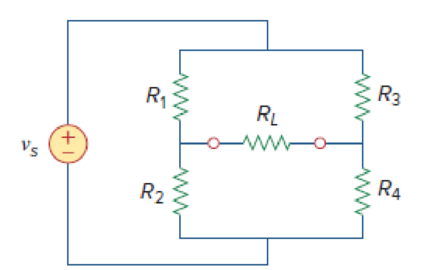
Figure 4.140
Find the maximum power transferred and maximum power absorbed by the load resistor
Answer to Problem 74P
The maximum power transferred and maximum power absorbed by the load resistor
Explanation of Solution
Given data:
Refer to Figure 4.140 in the textbook.
The voltage source is
Formula used:
Write the expression to find the power delivered to the resistor.
Here,
Calculation:
In the given circuit, find the Thevenin resistance by turning off the voltage source
The modified circuit is shown in Figure 1.
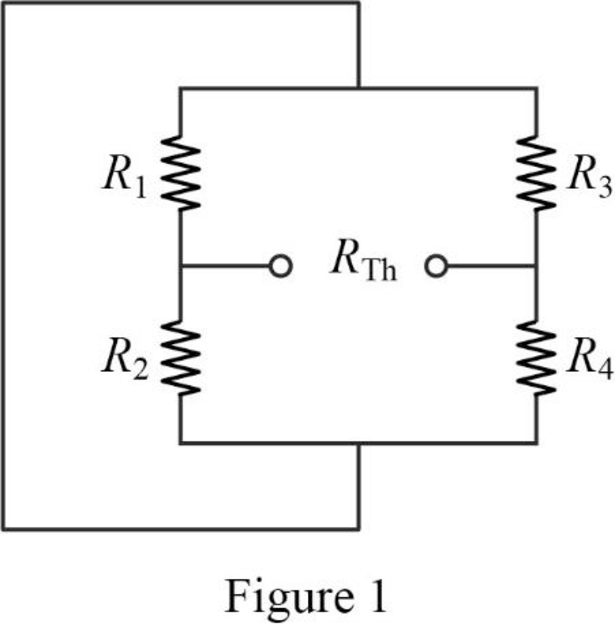
In Figure 1, the Thevenin resistance is,
Refer to Figure 4.139 in the textbook.
The given circuit is modified as shown in Figure 2 to find the Thevenin voltage.
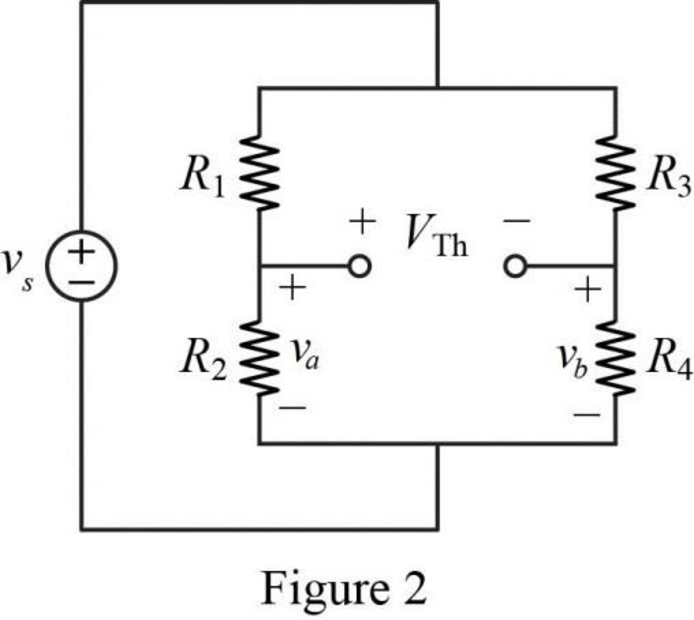
In Figure 2, the voltage
In Figure 2, the voltage
In Figure 2, apply Kirchhoff’s voltage law for the right bottom loop as follows.
Substitute
Substitute
Conclusion:
Thus, the maximum power transferred and maximum power absorbed by the load resistor
Want to see more full solutions like this?
Chapter 4 Solutions
Connect 2 Semester Access Card for Fundamentals of Electric Circuits


- Given the circuit in Fig. 4.117, obtain the Norton equivalent as viewed from terminals:arrow_forwardNumber 4.29 Use source transformation to find correctly Vo in the circuit of Fig. 4.97.arrow_forwardFind the Thevenin equivalent circuit of the circuit in Fig. 4.34 to the left of the terminals.arrow_forward
- 4.70 Determine the maximum power delivered to the variable resistor R shown in the circuit of Fig. 4.136.arrow_forwardUsing the superstition theorem, how would I prove the second images problem, given that #2 (voltage source was replaced with a short) measured 5 amps, and #4 (had the current source replaced with an open circuit) measured 1.6 amps?arrow_forwardAnalyze the circuit provided in Figure 4 to obtain the following: Norton equivalent of the network Thévenin Equivalent of the same network Use either to calculate iL for RL = 0Ω, 1Ω, 4.923Ω, and 8.107Ωarrow_forward
- A black box with a circuit in it is connected to a variable resistor. An ideal ammeter (with zero resistance) and an ideal voltmeter (with infinite resistance) are used to measure current and voltage as shown in Fig. 4.143.arrow_forward"SUPERPOSITION THEOREM" Please Find the Vo Using SUPERPOSITION THEOREM thankyou very much! I've included a cicruit app to check if your answer was correct and close to the value of currents and voltages which is 0.5V thankyou! I've been testing simple circuits to practice problems using different theorems,I appreciate you very much Thankyou!arrow_forward11 Kelvin Double Bridge is used for the measurement of larger value resistance. Select one: True Falsearrow_forward
- Teaching values through exhortation can be done with the help of ____________ a. Friends b. Computers c. Neighbors d. Stories with moral lessonsarrow_forwardProblem 4.9 a.) Find the Norton equivalent circuit of Fig. 4.8 external to the resistor R. b) Convert the Norton equivalent to Thevenin equivalent using source transformation. c) Compare the results with part (b) to your answer in Problem 4.8 (a)arrow_forwardUsing, necessarily, the superposition method, calculate the voltage that is applied on the terminals of the current source.arrow_forward
 Introductory Circuit Analysis (13th Edition)Electrical EngineeringISBN:9780133923605Author:Robert L. BoylestadPublisher:PEARSON
 Delmar's Standard Textbook Of ElectricityElectrical EngineeringISBN:9781337900348Author:Stephen L. HermanPublisher:Cengage Learning
 Programmable Logic ControllersElectrical EngineeringISBN:9780073373843Author:Frank D. PetruzellaPublisher:McGraw-Hill Education
 Fundamentals of Electric CircuitsElectrical EngineeringISBN:9780078028229Author:Charles K Alexander, Matthew SadikuPublisher:McGraw-Hill Education
 Electric Circuits. (11th Edition)Electrical EngineeringISBN:9780134746968Author:James W. Nilsson, Susan RiedelPublisher:PEARSON
 Engineering ElectromagneticsElectrical EngineeringISBN:9780078028151Author:Hayt, William H. (william Hart), Jr, BUCK, John A.Publisher:Mcgraw-hill Education,