
Concept explainers
Videos
Consider the bridge circuit of Fig. 4.148. Is the bridge balanced? If the 10-kΩ resistor is replaced by an 18-kΩ resistor, what resistor connected between terminals a-b absorbs the maximum power? What is this power?
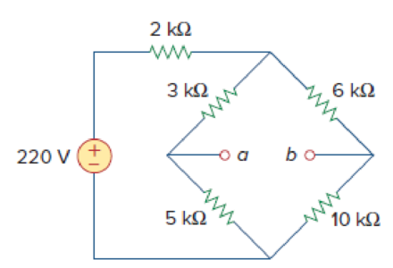
Figure 4.148
Find whether the bridge circuit of Figure 4.148 is balanced. Also find the value of the load resistor connected between the terminals a-b of the circuit and the maximum power absorbed by the load resistor.
Answer to Problem 92P
The bridge circuit is balanced when
Explanation of Solution
Given data:
Refer to Figure 4.148 in the textbook.
The voltage source is
Calculation:
For a bridge to be balanced, the voltage measured at terminals a-b should be zero.
The given circuit is modified as shown in Figure 1.
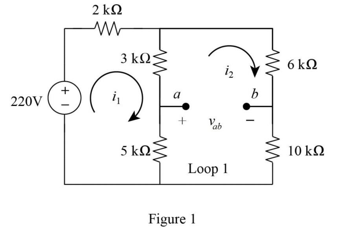
In Figure 1, apply Kirchhoff’s voltage law at loop
In Figure 1, apply Kirchhoff’s voltage law at loop
Substitute equation (2) in equation (1) as follows,
Simplify the equation as follows,
Substitute
In Figure 1, apply Kirchhoff’s voltage law at loop 1 as follows.
Substitute
As the voltage
In Figure 1, when the
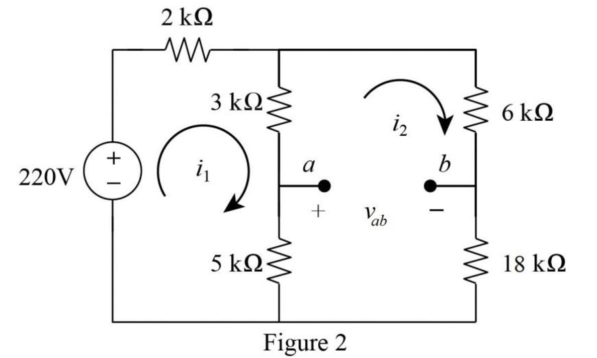
In Figure 2, apply Kirchhoff’s voltage law at loop
In Figure 2, apply Kirchhoff’s voltage law at loop
Substitute
Simplify the equation as follows,
Substitute
In Figure 2, the voltage
Substitute
Since the voltage
Refer to Figure (2).
In Figure (2), find the Thevenin resistance by turning off the
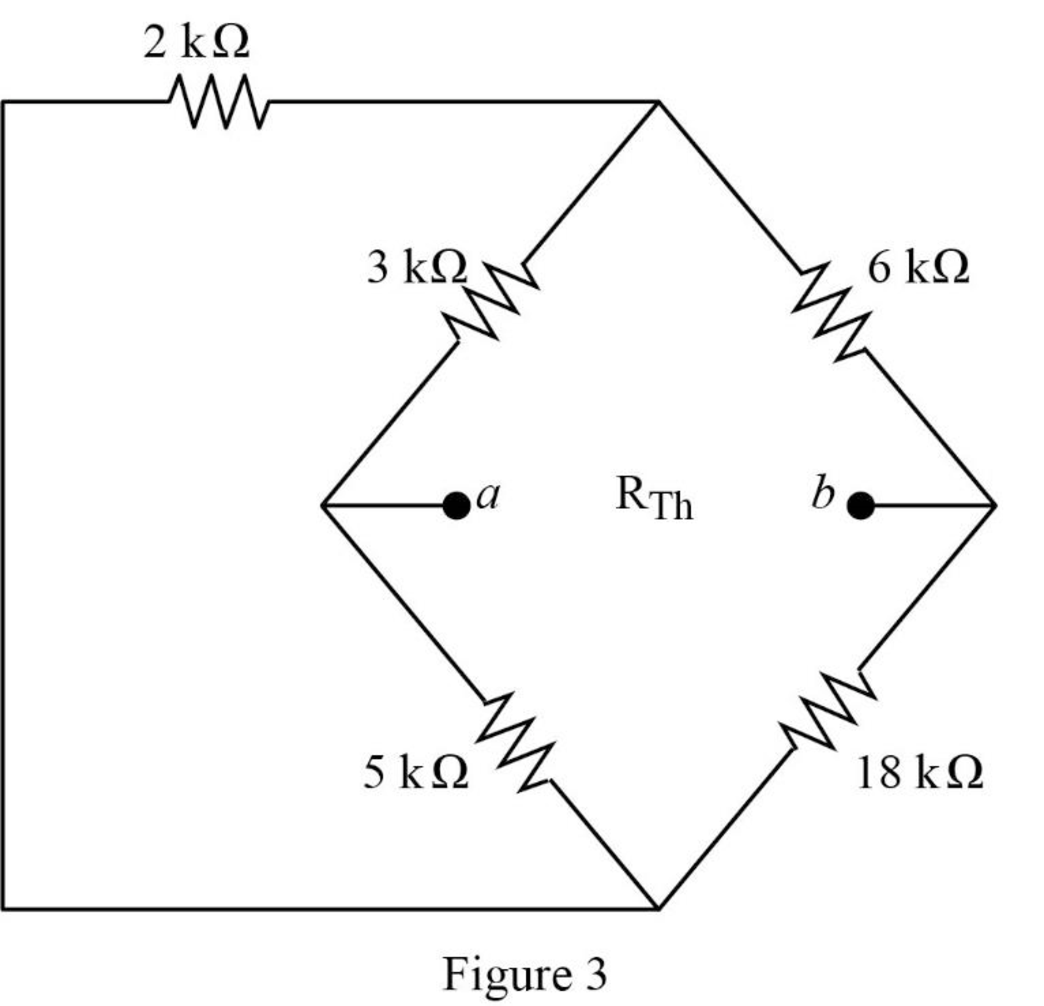
In Figure 3,
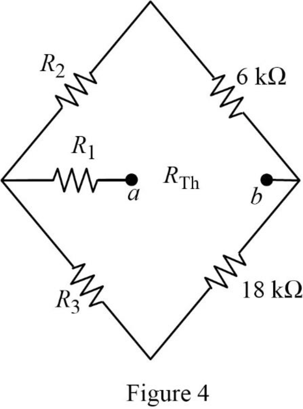
For the wye connection in Figure 4, the value of the resistor
For the wye connection in Figure 4, the value of the resistor
For the wye connection in Figure 4, the value of the resistor
Figure 4 is modified as shown in Figure 5.
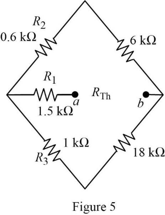
In Figure 5, the Thevenin resistance is,
Simplify the equation as follows,
For maximum power transfer,
The maximum power absorbed by the load resistor is,
Substitute
Conclusion:
Thus, the bridge circuit is balanced when
Want to see more full solutions like this?
Chapter 4 Solutions
Fundamentals of Electric Circuits


- 4.57 Obtain the Thevenin and Norton equivalent circuitsat terminals a-b for the circuit in Fig. 4.123.arrow_forwardA black box with a circuit in it is connected to a variable resistor. An ideal ammeter (with zero resistance) and an ideal voltmeter (with infinite resistance) are used to measure current and voltage as shown in Fig. 4.143.arrow_forward"SUPERPOSITION THEOREM" Please Find the Vo Using SUPERPOSITION THEOREM thankyou very much! I've included a cicruit app to check if your answer was correct and close to the value of currents and voltages which is 0.5V thankyou! I've been testing simple circuits to practice problems using different theorems,I appreciate you very much Thankyou!arrow_forward
- Analyze the circuit provided in Figure 4 to obtain the following: Norton equivalent of the network Thévenin Equivalent of the same network Use either to calculate iL for RL = 0Ω, 1Ω, 4.923Ω, and 8.107Ωarrow_forwardA 24V battery with 1Ω internal resistance, a 12V battery with 0.1Ω internal resistance and a 4Ω resistor are connected in parallel. The circuit supplies a 60W, 12V lamp. Compute for the terminal voltage of the 24V battery using any circuit theorem.arrow_forwardCalculate the Thevenin equivalent circuit seen through the terminals (a, b) & draw the equivalent mThevenin equivalent.arrow_forward
 Introductory Circuit Analysis (13th Edition)Electrical EngineeringISBN:9780133923605Author:Robert L. BoylestadPublisher:PEARSON
 Delmar's Standard Textbook Of ElectricityElectrical EngineeringISBN:9781337900348Author:Stephen L. HermanPublisher:Cengage Learning
 Programmable Logic ControllersElectrical EngineeringISBN:9780073373843Author:Frank D. PetruzellaPublisher:McGraw-Hill Education
 Fundamentals of Electric CircuitsElectrical EngineeringISBN:9780078028229Author:Charles K Alexander, Matthew SadikuPublisher:McGraw-Hill Education
 Electric Circuits. (11th Edition)Electrical EngineeringISBN:9780134746968Author:James W. Nilsson, Susan RiedelPublisher:PEARSON
 Engineering ElectromagneticsElectrical EngineeringISBN:9780078028151Author:Hayt, William H. (william Hart), Jr, BUCK, John A.Publisher:Mcgraw-hill Education,